FAQs:
What is an RF attenuator?
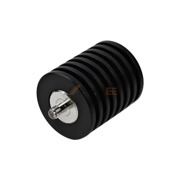
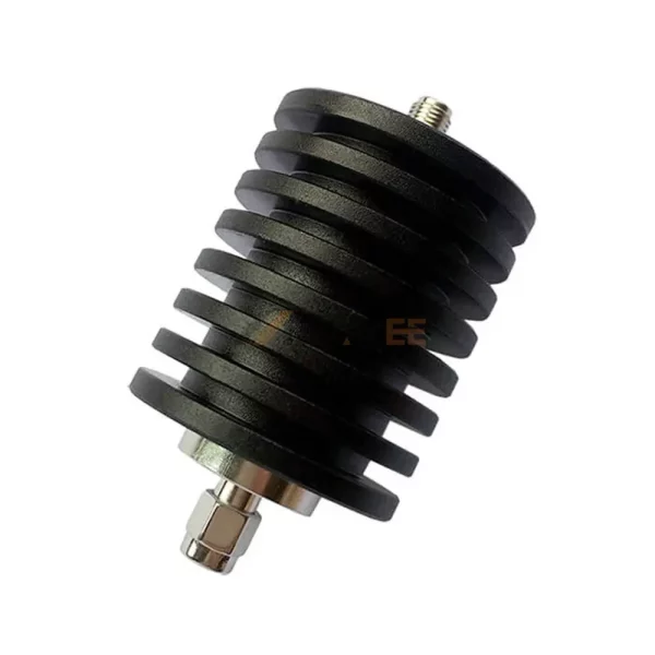
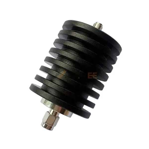
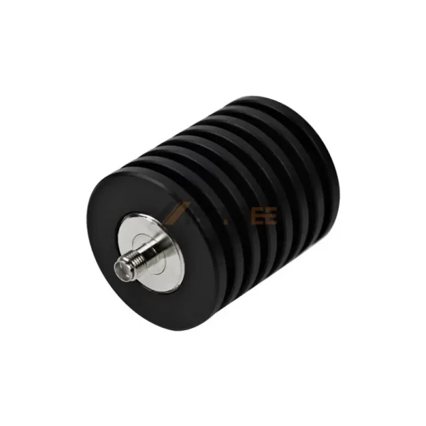
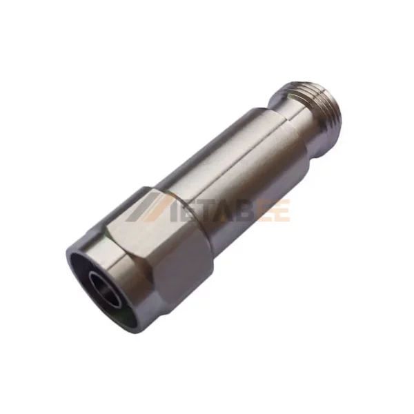
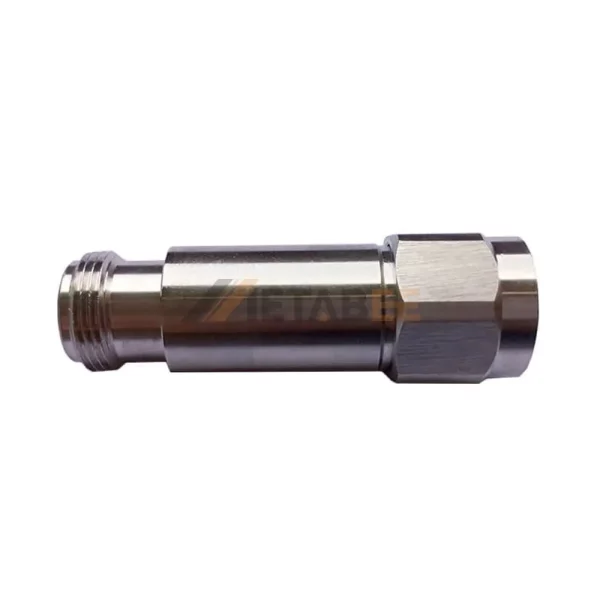
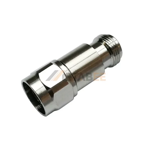
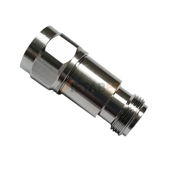
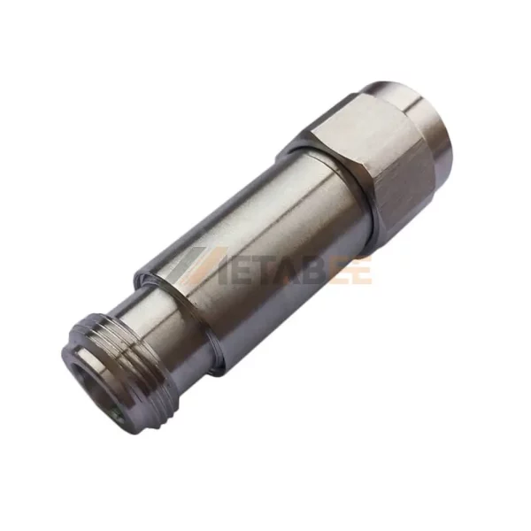
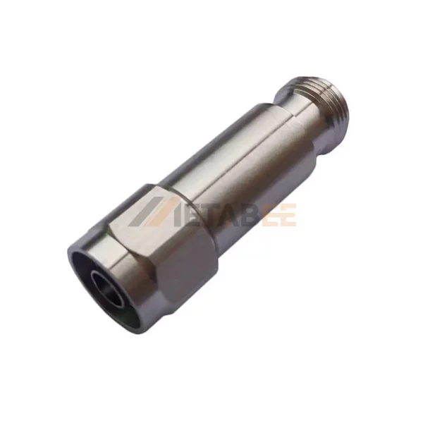
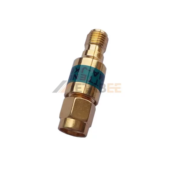
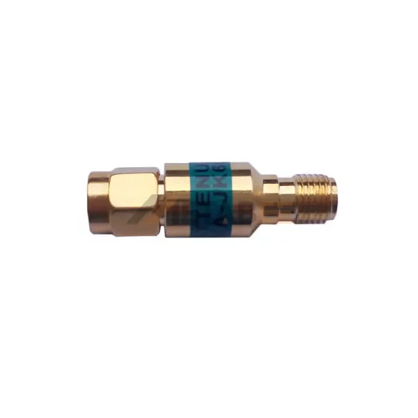
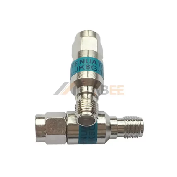
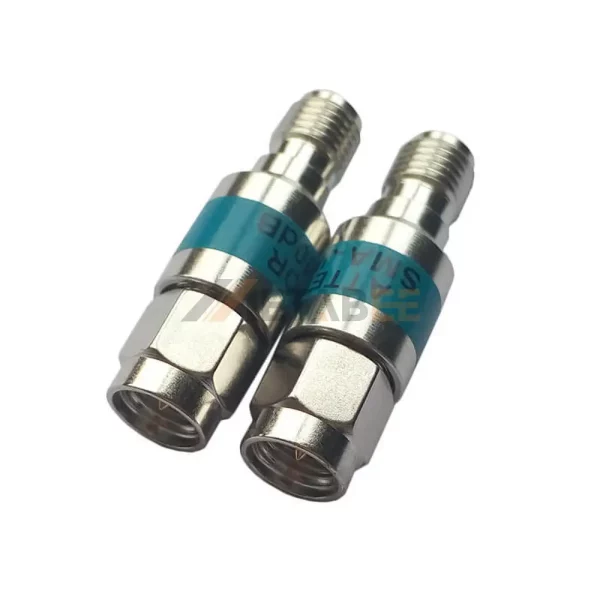
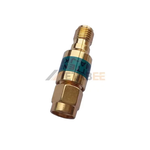
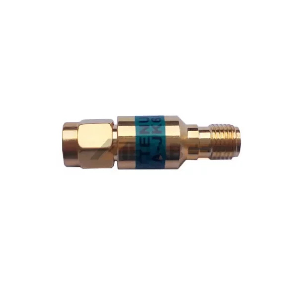
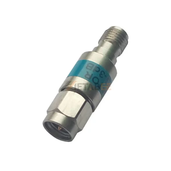
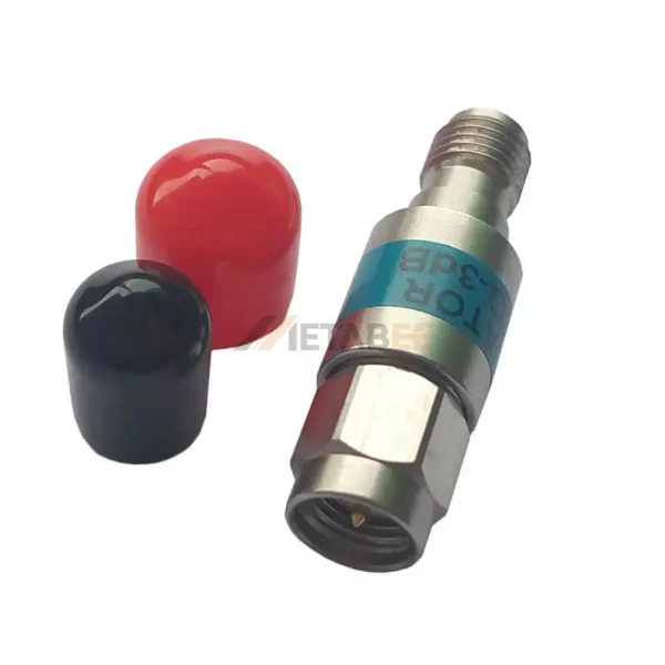
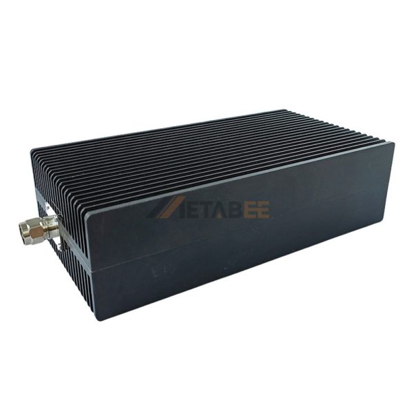
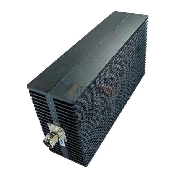
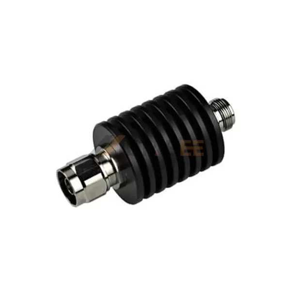
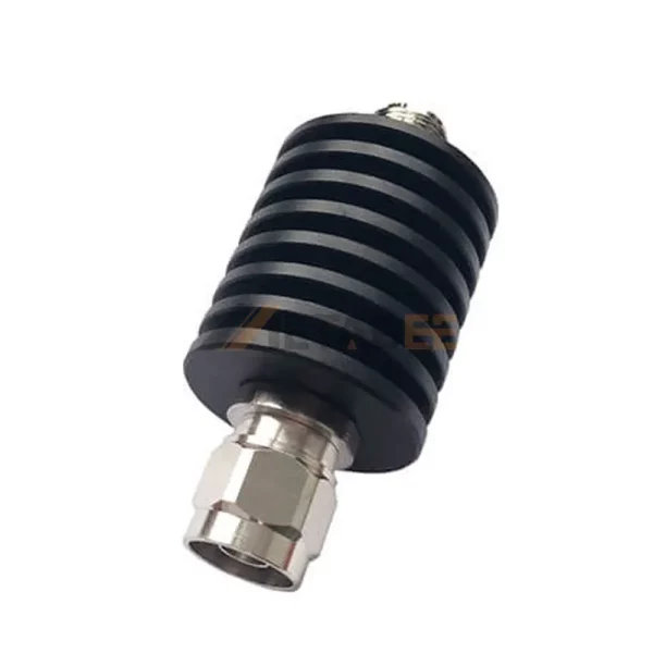
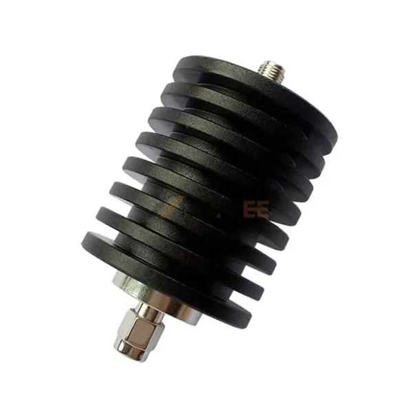
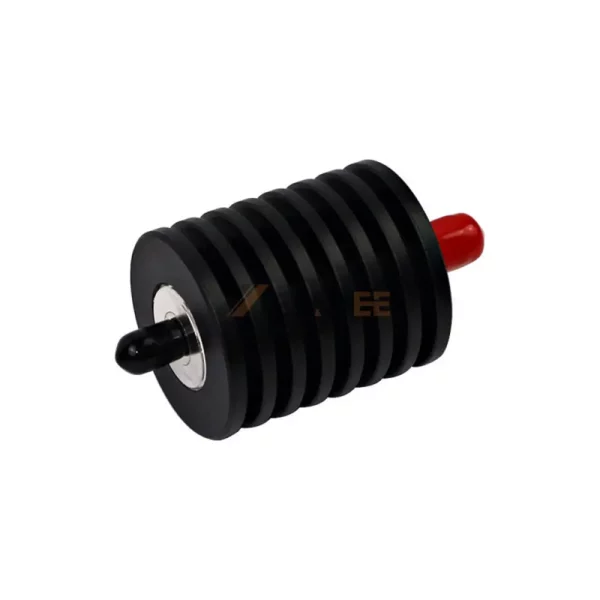
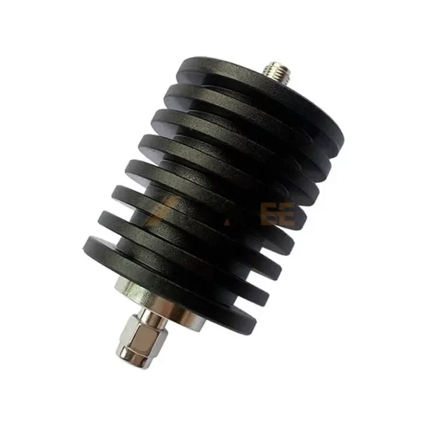
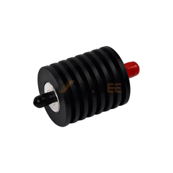
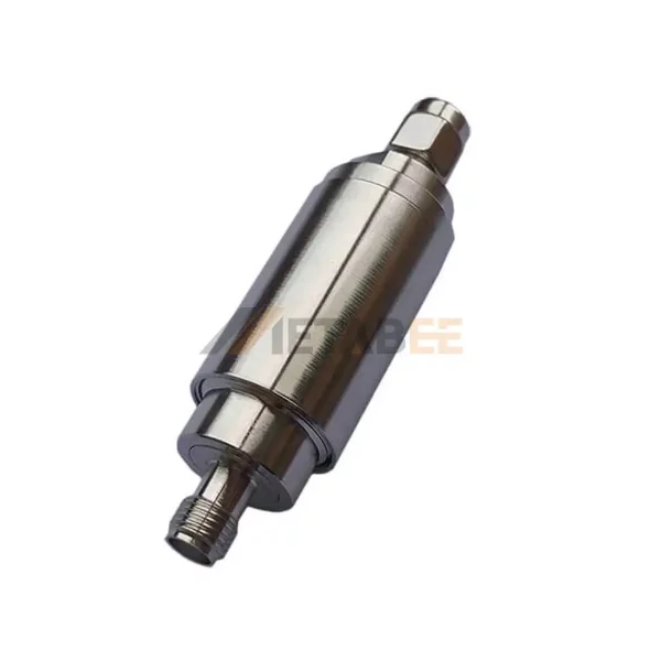
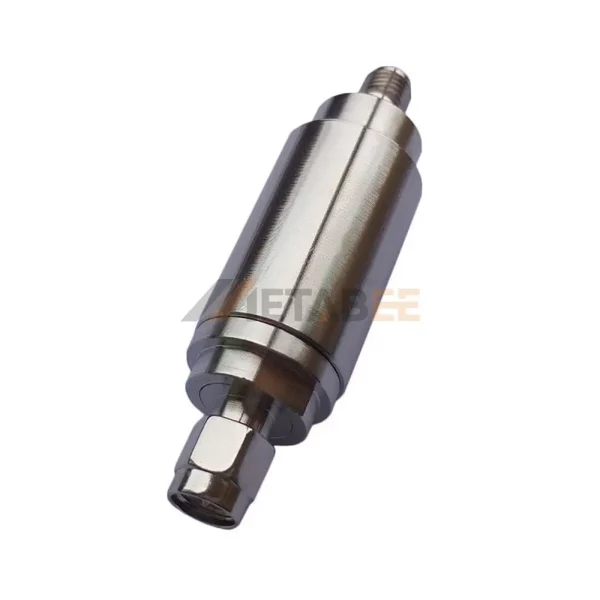
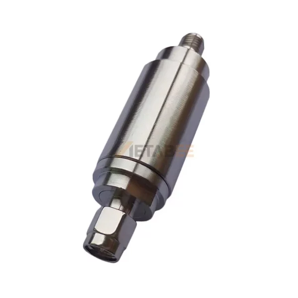
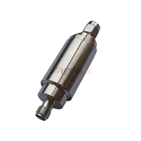
An RF attenuator is a passive electronic device that reduces the amplitude or power of an RF signal without significantly distorting its waveform. Think of it like a "volume knob" for RF signals..
Why are RF attenuators used?
They are used to protect sensitive equipment from high signal levels, ensure proper impedance matching to minimize reflections and VSWR, and enable controlled signal testing and calibration.
What types of connectors are commonly found on RF attenuators?
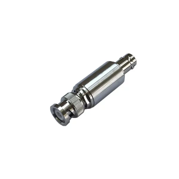
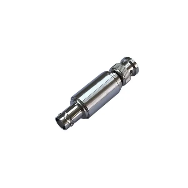
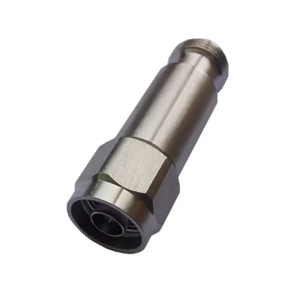
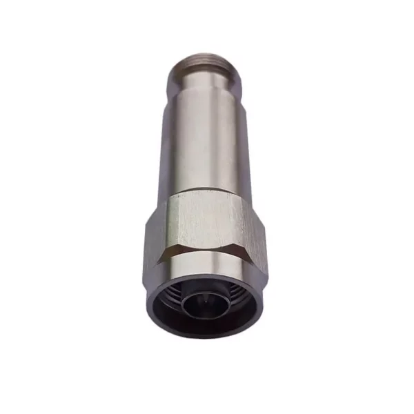
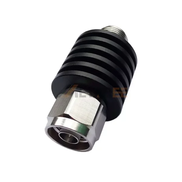
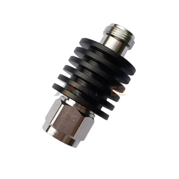
Common RF connectors include SMA, N-type, BNC, and DIN, depending on the frequency range and power level of the application.
How do you choose the right attenuation value?
Attenuation is specified in decibels—e.g., 3 dB halves the power, 6 dB reduces to one quarter, 10 dB to one
tenth. Select based on the desired output power relative to input to prevent overload.
What are the different types of RF attenuators?
Common types include:
Fixed attenuators: Provide a constant, unchangeable attenuation level (e.g., 3 dB, 10 dB).
Variable attenuators: Allow for manual adjustment of the attenuation level.
Step attenuators: Offer a series of fixed attenuation steps that can be selected.
Programmable attenuators: Electronically controllable, often used in automated test systems.
What are the key specifications to consider when choosing an RF attenuator?
Important specifications include:
Attenuation value : The amount of signal reduction.
Frequency range : The range over which the attenuator operates effectively.
Power handling : The maximum RF power the attenuator can dissipate without damage.
Impedance : Typically 50 or 75 ohms for RF applications.
VSWR: A measure of how well the attenuator is impedance-matched, indicating minimal signal reflection.
Connector type: SMA, N-type, BNC, DIN.
