
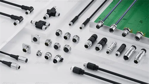
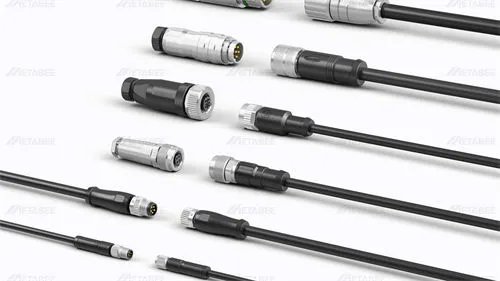
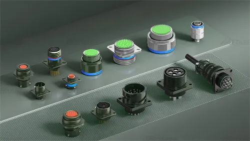
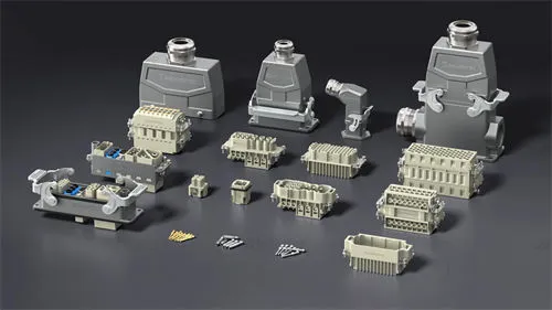
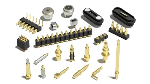
A circular connector is a multi-pin electrical interconnect with a cylindrical housing and circular contact arrangement. These round connectors transmit power, analog signals, and high-frequency data in demanding applications such as industrial automation, aerospace, and medical devices.
Their round design helps distribute mechanical stress, resist vibration and shock, and support 360° O-ring compression for environmental sealing up to IP68/IP69K. Proper shielding also helps protect against electromagnetic interference (EMI).
Choosing the right option from the various circular connector types involves evaluating locking mechanisms, metric (M-series) or military standards, pin density, and termination styles. This guide simplifies selection with a four-dimensional classification framework, a comparison matrix, and a four-step selection method.
What Are Circular Connectors?
Definition
Circular connectors, also known as circular interconnects, feature a cylindrical design with multiple electrical contacts. They reliably transmit power, electrical signals, and data between cables and equipment. ITT first introduced circular connectors in the 1930s for military aircraft. Today, these circular electrical connectors serve a wide range of applications, including industrial automation, sensors, robotics, transportation, and medical equipment.
Their cylindrical shape gives round connectors a higher strength-to-weight ratio than connectors of other shapes. This structure also improves resistance to environmental stress and accidental disconnection.
Physical benefits:
- Even Stress Distribution: Rounded bodies eliminate sharp corners and distribute loads evenly, resisting impact, shock, and radial crushing.
- Uniform 360° Sealing: Circular channels apply even radial pressure to O-rings, blocking moisture, dust, and washdown chemicals with IP67, IP68, and IP69K protection.
- 360° EMI Shielding: Metal shells provide full contact with braided cable shields, blocking electromagnetic interference (EMI) and radio frequency interference (RFI).
- Blind Mating: Alignment keyways guide plug insertion, enabling quick, tactile mating and locking in dark spaces or with heavy gloves.
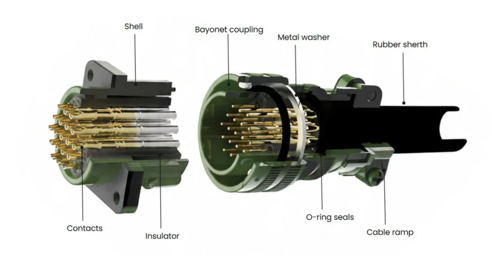
Core Components
1. Contacts: Consist of male pins and female sockets, which establish electrical connections to transmit power and signals.
2. Insulator / Insert: Also known as an insulating base or insert plate, it arranges contacts in the specified positions and spacing, ensuring electrical insulation between contacts and between contacts and the shell. Common materials include PPS, PBT, and PEEK.
3. Shell / Housing: Provides mechanical protection for the internal insulator and contacts, ensures proper alignment when mating the plug and receptacle, and secures the connector to the equipment. Housing options range from rugged aluminum alloy and stainless steel to cost-effective circular plastic connector bodies made from high-strength engineering resins.
4. Coupling Mechanism: Connects and locks the plug and receptacle to prevent accidental disconnection caused by vibration or external forces. Common coupling styles include threaded locking, bayonet, and push-pull coupling.
5. Accessories: Include metal washer, cable ramp, and O-ring seals. These components secure cables mechanically, reduce bending and pulling stress, and provide reliable protection against water and dust.
MIL-C-5015 Sonnector Structure
How to Classify Circular Connector Types: The 4 Core Dimensions
Circular connectors can be classified by 4 key dimensions, each describing a different aspect of their design and function.
| Classification | What It Defines | Common Types |
|---|---|---|
| Locking Mechanism | How the connector mates and locks | Threaded, Bayonet, Push-Pull |
| Mounting Style | How the connector is installed | Cable-Mount, Panel-Mount, PCB-Mount |
| Electrical Function | The type of electrical transmission supported | Signal, Power, Data, Hybrid |
| Connector Series and Standards | The product family or applicable specification | M-Series, DIN-standard, MIL-Spec |
These dimensions are complementary rather than mutually exclusive. For example, an M12 connector can have a threaded coupling, a metal housing, and a panel-mount configuration. The following sections examine each classification in detail.
Circular Connectors by Locking Mechanism
Circular connector locking mechanisms determine how a plug mates with a receptacle and stays securely connected. The three common types of circular connectors are threaded, push-pull, and bayonet designs. Each offers different advantages in connection speed, locking security, and ease of operation.
Threaded Circular Connectors
Threaded circular connectors use mating threads on the coupling nut and receptacle to secure the connection. Turning the coupling nut tightens the plug against the receptacle.
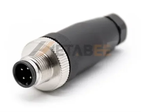
Key Characteristics
- Secure threaded locking helps prevent accidental disconnection.
- Suitable for applications exposed to vibration and mechanical stress.
- Requires rotational clearance and more time for connection and disconnection.
Typical Applications: Industrial machinery, outdoor equipment, and transportation systems.
Push-Pull Circular Connectors
Circular push-pull connectors use an internal locking mechanism that engages when the plug is pushed into the receptacle. Depending on the design, a designated sleeve or release mechanism is used to disconnect the plug. The Swiss company LEMO first pioneered this interface. Today, it is widely used in medical diagnostic and precision test equipment, delivering fast blind mating and over 5,000 mating cycles.
Looking for a reliable and cost-effective alternative? We manufacture precision circular push-pull connectors that mate directly with original LEMO B, K, and T series interfaces. Request a LEMO Compatibility Guide and Free Engineering Samples
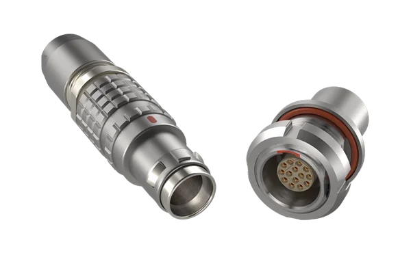
Key Characteristics
- Fast connection and release with minimal effort.
- Ideal for frequent mating and unmating.
- Requires less rotational clearance than threaded circular connectors.
Typical Applications: Medical equipment, test and measurement instruments, and portable devices.
Bayonet Circular Connectors
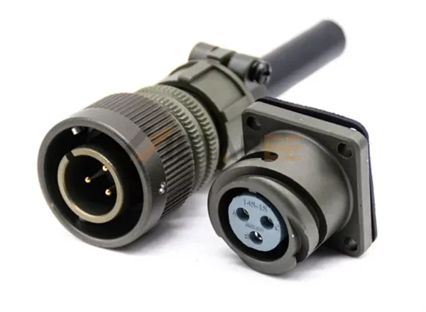
Circular bayonet connectors use pins and matching slots or ramps to secure the plug with a short rotational movement.
Key Characteristics
- Quick connection with a short twist.
- Positive mechanical engagement provides clear locking feedback.
- Combines fast operation with mechanical retention.
Typical Applications: Industrial equipment, transportation systems, and communication devices.
Threaded vs. Push-Pull vs. Bayonet Coupling Methods
The following comparison highlights the main differences between these three circular connector locking mechanisms.
| Feature | Threaded Coupling | Push-Pull Coupling | Bayonet Coupling |
|---|---|---|---|
| Locking Method | Threaded rotation | Push-to-lock | Short rotational turn |
| Connection Speed | Generally slower | Fast | Fast |
| Key Advantage | Secure threaded engagement | Quick, easy operation | Fast locking with positive engagement |
| Space Requirement | Needs rotational clearance | Minimal rotational clearance | Needs some rotational clearance |
| Best For | Secure, stable connections | Frequent mating and unmating | Quick connections with mechanical retention |
Circular Connectors by Industry Standards
Industry standardization guarantees mechanical interchangeability, pinout consistency, and multi-vendor sourcing across global OEM supply chains. Three standard architectures dominate industrial machinery, military defense, and commercial systems: circular metric connectors, Mil-Spec standards, and circular DIN designs.
Circular Metric Connectors (IEC 61076 Series)
In circular metric connectors, the designation “M” indicates the nominal outer thread diameter in millimeters. Metric connector size affects panel footprint, contact capacity, cable diameter, and available coupling mechanisms.
However, connector size alone does not determine electrical performance. Consider contact layout, coding, current rating, IP rating, and termination style when selecting metric circular connectors.
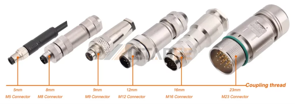
The table below compares standard circular connectors from compact M5 to larger M40 sizes.
| Size / Series | Available Pin Counts | Typical Coupling Style | Max Electrical Limits | Standard IP Rating | Applications |
|---|---|---|---|---|---|
| M5 | 3, 4 | Screw thread (M5×0.5) | 60V / 1A | IP67 | Miniature proximity sensors, micro-pneumatic valves, optical inspection heads |
| M8 | 3, 4, 5, 6, 8 | Threaded (M8×1.0) or snap-in | 60V / 1.5–4A | IP67 to IP69K | Proximity switches, photoelectric sensors, pneumatic cylinder sensors, compact I/O blocks |
| M9 | 2 to 8 | Threaded, quick-lock, bayonet | 125V / 1–4A | IP67 | Portable medical diagnostic devices, precision test & measurement probes, laboratory instrumentation |
| M12 | 3, 4, 5, 8, 12, 17 | Threaded (M12×1.0) or push-pull | Up to 630V / 16A (coding-dependent) | IP67, IP68, IP69K | Distributed I/O blocks, Industrial Ethernet (PROFINET/EtherCAT), machine vision cameras, 24V DC field power |
| M16 | 2 to 24 | Screw thread (M16×0.75) | 250V / 3–7A | IP40 to IP68 | Load cells, industrial weighing systems, rotary encoders, pneumatic valve terminals |
| M23 | 6 to 19 | Threaded or Speedtec quick-lock | 630V / 28A | IP67 to IP68 | Industrial servo motor power, holding brakes, digital encoder & resolver feedback |
| M40 | 6, 8 | Threaded or quick-lock | 600V / 70A | IP67 | Heavy CNC spindle drives, large gantry servo motors, high-current machine tool feeds |
Among these sizes, M12 circular connectors are especially common in industrial automation because different coding options support signal, data, and power connections.
M12 Connector Coding Guide
| Coding | Typical Function | Common Application |
|---|---|---|
| A-coded | Sensors and general signals | Sensors and actuators |
| B-coded | Fieldbus | Applicable PROFIBUS systems |
| D-coded | Ethernet up to 100 Mbps | Fast Ethernet and applicable PROFINET systems |
| X-coded | High-speed Ethernet, commonly up to 10 Gbps | High-bandwidth industrial networks |
| S-coded | AC power | Industrial power connections |
| T-coded | DC power | DC power distribution |
| K-coded | Higher-power AC | Applicable motor power systems |
| L-coded | DC power | Industrial actuators and power distribution |
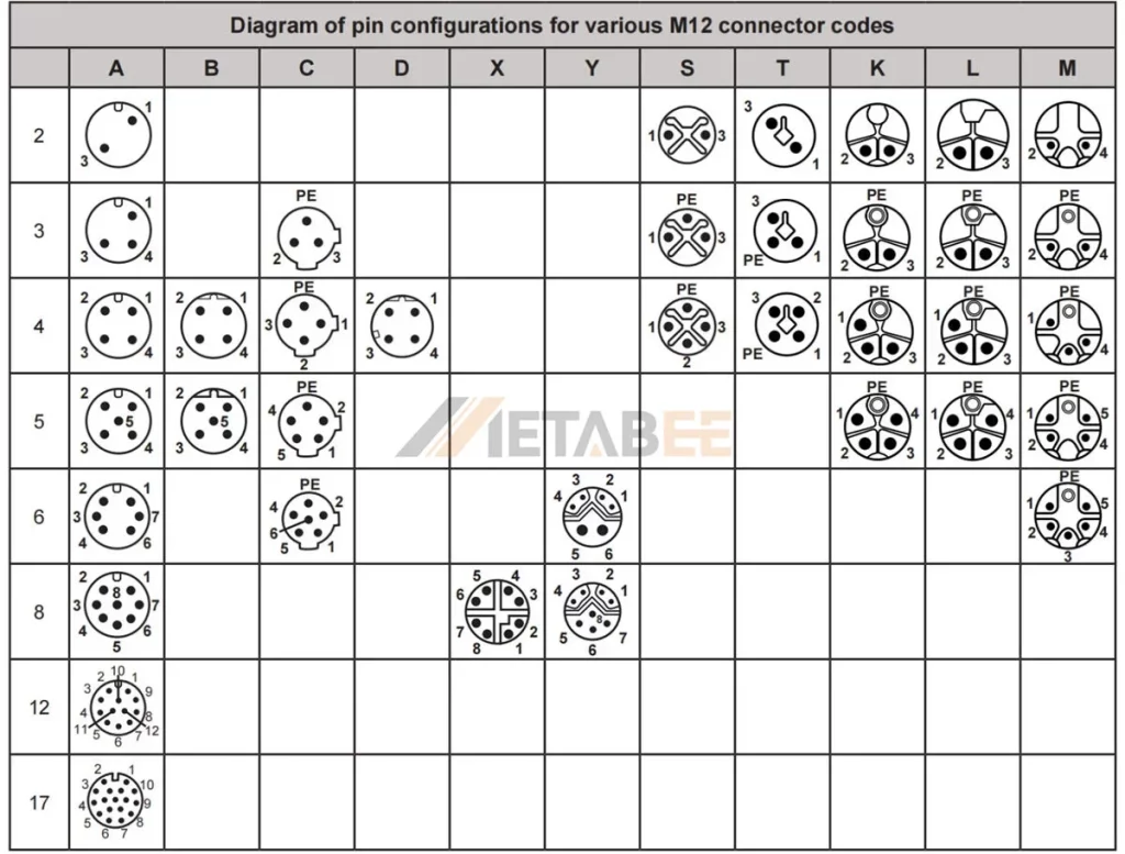
Coding helps identify the mating interface, but it does not guarantee compatibility by itself. Always check the pin assignment, electrical ratings, cable specification, and applicable product standard.
Explore Metabee’s M12 circular connectors and M12 cable assemblies for available configurations.
Related Posts:M12 Connector Types: A Visual Guide for Identifying and Selecting the Right Connector
MIL-Spec Circular Connectors
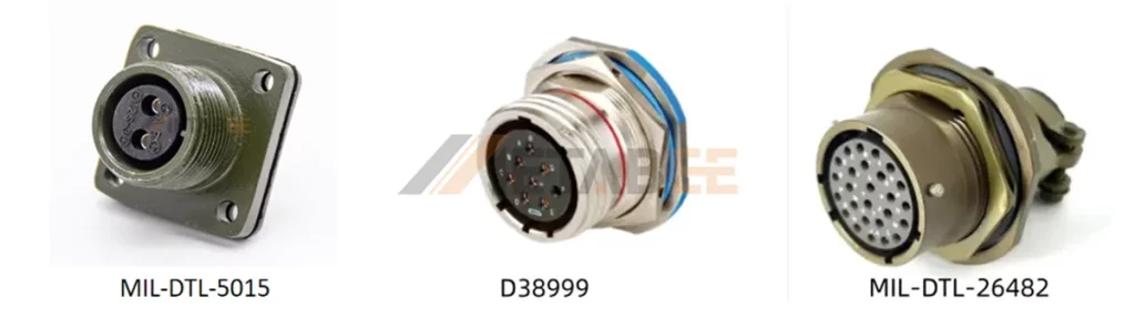
MIL-Spec circular connectors are rugged electrical interconnects designed to meet specific U.S. military requirements. Commonly identified by MIL-DTL specification numbers or legacy MIL-C designations, they serve defense, aerospace, and other demanding applications.
Military standards cover circular, rectangular, Micro-D, and rack-and-panel connectors. Among these, circular military connectors are widely used in harsh environments for their compact size, mechanical strength, and secure coupling.
Three common families include MIL-DTL-38999, MIL-DTL-5015, and MIL-DTL-26482.
Quick Overview of the Three Major Military Connector Standards
| Standard | Connector Type | Coupling Mechanism | Typical Applications |
| MIL-DTL-5015 | General-Purpose Military Circular Connectors | Threaded Coupling | Power, Industrial Equipment |
| MIL-DTL-38999 | High-Density Aerospace Connectors | Threaded Coupling with Composite Keying | Aerospace, Aviation, Advanced Equipment |
| MIL-DTL-26482 | Medium-Sized Circular Connectors | Threaded / Bayonet Coupling | Military, Communications, Vehicles |
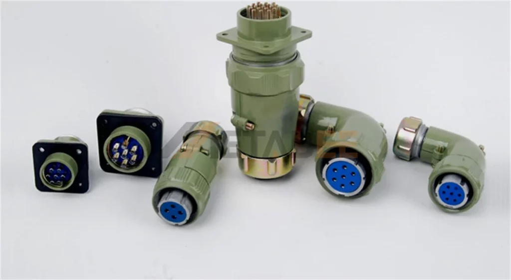
MIL-DTL-5015 (SAE AS50151)
The heavy-duty workhorse for military ground vehicles and industrial power transmission. MIL-DTL-5015 connectors feature medium-to-heavy weight aluminum shells, thick wall sections, and high-amperage machined contacts. They originally used fine threaded couplings, though modern industrial variants (such as VG95234) often upgrade to reverse-bayonet locks for faster mating.
MIL-DTL-38999 (D38999)
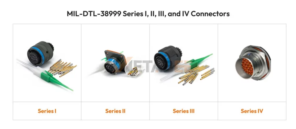
The flagship standard for modern aerospace and defense electronics. D38999 connectors offer high-density contact layouts (up to 128 pins), scoop-proof shells that prevent pin damage during blind mating, and strong EMI shielding.
- Series I: Bayonet coupling with a scoop-proof shell for quick disconnects.
- Series II: Low-profile bayonet design that saves weight and panel depth (non-scoop-proof).
- Series III: Self-locking, triple-start threaded coupling. It delivers the highest vibration resistance and serves as the industry’s most popular harsh-environment standard.
- Series IV: Breech-lock coupling for rapid mating and scoop-proof contact protection.
MIL-DTL-26482 (Series I & II)
A compact, miniature bayonet-coupling connector family (commonly recognized by MS3112 and MS3116 part numbers). Utilizing a fast three-point bayonet lock, MIL-DTL-26482 connectors provide a lighter, smaller-diameter alternative to MIL-DTL-5015 for commercial aviation, military radios, and industrial control cabinets.
Explore Metabee’s rugged military circular connectors with custom cable assembly options available. Download our dedicated D38999 catalog, MIL-DTL-5015 catalog, or MIL-DTL-26482 catalog for detailed product specifications, or contact our engineering team to discuss your application and connector requirements.
Related Posts:
- D38999 Connector Guide: Understanding the Series and Shell Styles
- MIL-DTL-26482 Connector Guide (MS3112 & MS3116): Series, Part Numbers, Specs & Selection
Circular DIN Connectors
The term DIN connector refers to a class of electrical connectors that adhere to the standards set by the Deutsches Institut für Normung (DIN), which translates to the German Institute for Standardization. They include multi-pin circular interfaces used in audio equipment, electronic devices, and selected industrial applications.
Overview of Major Standard Circular Connectors
| Standard Category | Common Types | Classification Basis |
| Circular Metric Connectors | M5, M8, M12, M23, M40 | Metric thread size and connector configuration |
| MIL-Spec Circular Connectors | MIL-DTL-38999, MIL-DTL-5015, MIL-DTL-26482 | Applicable military specification and connector series |
| Circular DIN Connectors | DIN-standardized circular interfaces | Applicable DIN standard and interface design |
Circular Connectors by Electrical & Power Function
Circular electrical connectors can be classified by their primary transmission function:
- Signal connectors: Transmit control signals between sensors, actuators, and controllers.
- Data connectors: Support communication across industrial networks and data interfaces.
- Power connectors: Deliver electrical power to motors, drives, and other equipment.
- Hybrid connectors: Combine power and signal contacts in a single connector.
Some circular connectors support multiple functions, depending on their contact configuration and design.
Circular Connectors by Mounting Style
Circular connectors are available in different mounting configurations to accommodate equipment layouts, circuit board designs, and cable connections.
Panel-Mount Connectors
Panel-mount connectors secure to equipment panels or enclosures, providing fixed mating interfaces. Common forms include front-mount and rear-mount receptacles, flange-mount connectors, and bulkhead feed-through connectors.
PCB-Mount Connectors
PCB-mount connectors attach directly to printed circuit boards and provide interfaces between electronic circuits and external devices. Common designs include through-hole and surface-mount connectors.
Cable-Mount Connectors
Cable-mount connectors terminate on cables for direct equipment connections or inline connections between cables. Available forms include field-installable plugs, cable receptacles, and overmolded cable assemblies.
How to Choose the Right Circular Connector: 7 Key Factors
1. Operating Environment
The operating environment is the first consideration when selecting a circular connector. Dust, moisture, vibration, temperature, and chemical exposure determine the required IP rating and structural design.
2. Electrical Requirements
Match the connector’s electrical ratings to the system requirements. Key parameters include rated voltage, current rating, contact resistance, signal type, and insulation performance.
3. Mechanical Design and Space Constraints
Mechanical compatibility is essential. The connector’s dimensions, mounting style, and available installation space must match the equipment design. Common sizes include M5, M8, M9, M12, M16, M23and 7/8-inch connectors.
Metabee offers circular connectors in multiple sizes to meet different installation requirements. Their precision-engineered designs support smooth mating, wear resistance, and reliable signal transmission, with shielding options for EMI protection.
4. Coupling Mechanism
Threaded, bayonet, and push-pull coupling mechanisms affect connection security and mating efficiency. Threaded couplings are often preferred in industrial environments because of their resistance to vibration-induced loosening.
5. Shielding and Signal Integrity
For data transmission and sensitive signals, electromagnetic interference (EMI) and radio-frequency interference (RFI) shielding help maintain signal integrity and reduce interference in electrically noisy environments.
6. Durability and Mating Cycles
Connector durability depends on rated mating-cycle life, contact plating quality, and housing material. High-quality circular connectors can reduce maintenance requirements and extend service life.
7. Coding and Mating Polarization
Coding and polarization features help prevent mismating in applications with multiple connectors. Common options include A-coded, B-coded, and D-coded connectors, helping improve installation accuracy and reduce connection errors.
Conclusion
Mastering circular connector types comes down to four core dimensions: locking mechanism, industry standard, electrical function, and mounting style. In practice, specify metric M-series (M8, M12, M23) for factory automation and industrial Ethernet, MIL-Spec series (D38999, 5015, 26482) for extreme vibration and defense environments, and push-pull or bayonet designs for fast, high-cycle mating in tight spaces.
As trusted circular connector manufacturers, Metabee delivers precision-engineered interconnect solutions. Explore our circular connectors and download our product catalogs to compare pinout configurations, shell dimensions, and IP ratings. If your project involves harsh environmental limits, custom wire harnesses, or cross-reference replacements, contact our application engineers today for selection verification and free evaluation samples.
FAQs
Q1: What are the most common types of circular connectors?
A: Metric M-series connectors (M8, M12, M23) and MIL-Spec circular connectors (MIL-DTL-38999, 5015, 26482) are the two most widely used families, followed by medical push-pull connectors and classic circular DIN connectors.
Q2: What Is the Difference Between M12 A-Coded and X-Coded Connectors?
A: A-coded M12 connectors commonly handle sensor signals and general connections, while X-coded connectors support high-speed Ethernet up to 10 Gbps. See our M12 Coding Reference Post for more coding options.
Q3: When should I choose a plastic shell over a metal shell circular connector?
A: Choose a plastic-shell circular connector (CPC) for lightweight, cost-sensitive applications requiring electrical insulation and corrosion resistance. Choose a metal-shell circular connector for greater mechanical strength and EMI shielding in demanding environments.
Q4: What IP rating should I choose for waterproof circular connectors?
A: Industrial waterproof circular connectors typically use IP67, IP68, or IP69K ratings. Choose IP67 for outdoor splashes and brief 1-meter immersion. Select IP68 waterproof circular connectors for continuous underwater submersion, and specify IP69K for high-pressure, high-temperature washdowns.
Q5: What is the difference between circular connectors and rectangular connectors?
A: Circular connectors use cylindrical shells to deliver superior crush resistance, vibration tolerance, and uniform 360-degree environmental sealing. This makes circular connector types ideal for harsh external cable connections. Rectangular connectors pack higher pin counts into flat spaces and support modular inserts, making them better suited for internal PCBs, control cabinets, and rack-and-panel systems.
