
In the fast-paced world of industrial automation, reliability is not just a preference; it is an absolute requirement. At the heart of this reliable interconnectivity lies the M8 connector. Compact, rugged, and highly versatile, M8 connectors are the unsung heroes of modern smart factories, establishing critical links between sensors, actuators, and industrial control networks.
However, selecting the right connector is only half the battle. For electrical engineers, technicians, and procurement specialists, understanding the precise M8 connector pinout, the standard color codes, and the corresponding wiring diagrams is essential to prevent system failures, signal interference, or costly downtime.
In this comprehensive technical guide, we will dive deep into everything you need to know about M8 connector pinouts, ranging from standard 3-pin setups to high-density 8-pin configurations. Whether you are wiring a simple proximity sensor or laying out an industrial Ethernet network, this guide—brought to you by the interconnect experts at Metabee—will serve as your definitive resource.
- What is an M8 connector? An Overview of Standards
- Understanding M8 Coding Types: The Foundation of Proper Pinouts
- Comprehensive M8 Pinout, Color Code & Wiring Guide (3-Pin to 8-Pin)
- How to Select the Right M8 Connector for Your Application
- Related Products
- Conclusion & Choose Metabee for Your M8 Interconnect Solutions
- Frequently Asked Questions (FAQs)
What is an M8 connector? An Overview of Standards
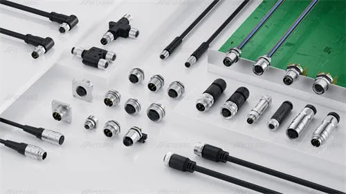
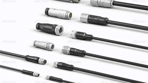
An M8 connector is a circular connector featuring an 8mm metric thread, designed primarily for industrial automation applications. Initially, it was developed to provide a secure and robust connection for sensors and switches in tight spaces. Over time, it has evolved to handle complex data transmission protocols.
The design and specifications of M8 connectors are strictly governed by international standards, most notably IEC 61076-2-104. This standard ensures global compatibility, meaning an M8 connector from a compliant manufacturer will seamlessly mate with standardized receptacles worldwide.
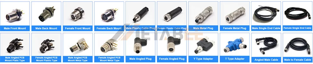
Key characteristics of M8 connectors include:
- Ruggedness: Designed to withstand harsh industrial environments, offering high resistance to vibration and mechanical shock.
- Ingress Protection: Typically rated at IP67 or IP68, ensuring they are dust-tight and highly resistant to moisture and water immersion.
- Versatility: Capable of handling power, analog signals, and high-speed digital data.
As a leading manufacturer, Metabee engineers M8 connectors that not only meet but exceed these stringent IEC standards, ensuring that your automated systems run continuously without interconnection failures.
Understanding M8 Coding Types: The Foundation of Proper Pinouts
Before diving into the specific pinouts, it is crucial to understand M8 “coding.” Coding refers to the physical mechanical keying (or polarization) inside the connector interface. This physical design prevents engineers from accidentally plugging a connector into the wrong port—a failsafe known as “poka-yoke” or mistake-proofing.
M8 connectors primarily utilize three coding types, each dictating a specific application and pin layout:
- A-Coded: The most common standard. Primarily used for DC power supply and standard signal transmission for sensors and actuators. Available in 3, 4, 6, and 8-pin variants.
- B-Coded: Less common in M8 than in M12, but occasionally used for specific Fieldbus networks (like Profibus) to prevent confusion with standard A-coded sensor lines. Typically found in 5-pin configurations.
- D-Coded: Specifically engineered for high-speed industrial data transmission, most notably Industrial Ethernet and PROFINET. It features a unique 4-pin arrangement.
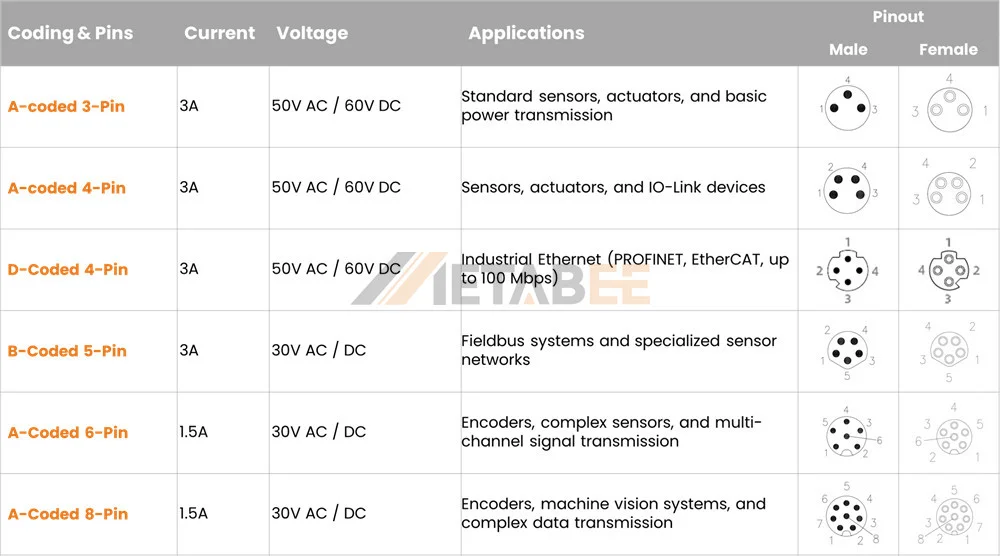
Ignoring the coding type will not only make physical mating impossible but could also lead to catastrophic short circuits if forced.
Comprehensive M8 Pinout, Color Code & Wiring Guide (3-Pin to 8-Pin)
To properly integrate M8 connectors into your system, you must understand how the physical pin layout (Pinout), the wire colors inside the cable (Color Code), and the electrical logic (Wiring Diagram) intersect. Below is the ultimate breakdown by pin count.
M8 3-Pin Connector (A-Coded)
The 3-pin A-coded M8 connector is the absolute standard for basic sensor connections, such as proximity switches and photoelectric sensors.
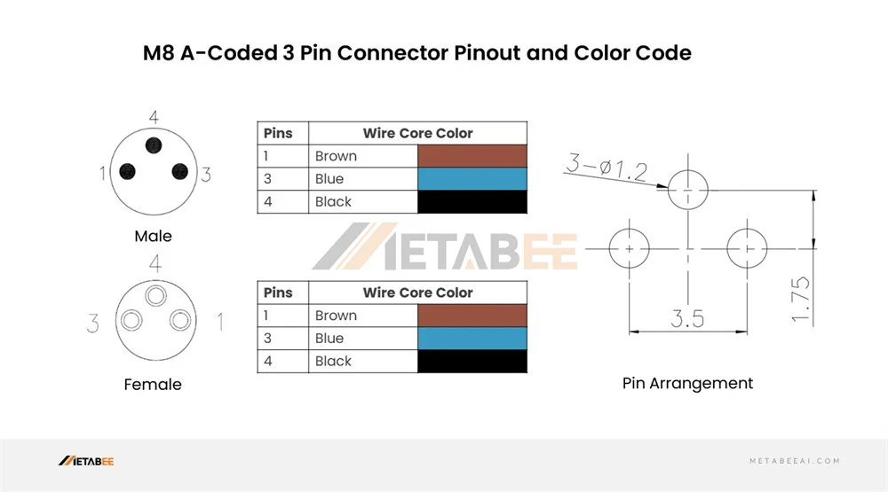
Pinout & Color Code Definition: Interestingly, in a standard 3-pin M8 connector, the physical layout skips Pin 2. The pins present are 1, 3, and 4.
- Pin 1: Brown (BN) – Used for Positive Power Supply (+VDC, typically 10-30V).
- Pin 3: Blue (BU) – Used for Negative Power Supply / Ground (-VDC / 0V).
- Pin 4: Black (BK) – Used for the Output Signal (Switching output).
Wiring Diagram Context: When integrating the M8 3-pin connector into a wiring diagram, you must consider the sensor type: PNP (sourcing) or NPN (sinking).
- In a PNP wiring diagram: The load is connected between the Black wire (Pin 4) and the Blue wire (Pin 3). When the sensor triggers, it sends positive voltage down the Black wire.
- In an NPN wiring diagram: The load is connected between the Black wire (Pin 4) and the Brown wire (Pin 1). When triggered, the sensor connects the Black wire to ground.
M8 4-Pin Connector Configurations
The 4-pin configuration is where M8 connectors become highly versatile, split primarily between two distinct coding types: A-Coded for dual-signal sensors and D-Coded for Ethernet.
4-Pin A-Coded (Sensor & Actuator Standard)
This builds upon the 3-pin design by introducing the previously skipped Pin 2.
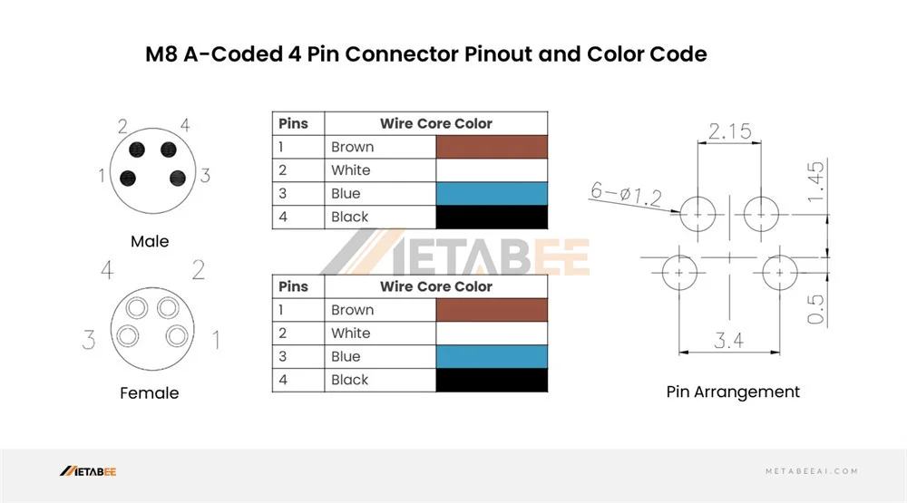
Pinout & Color Code Definition:
- Pin 1: Brown (BN) – Power (+)
- Pin 2: White (WH) – Secondary Signal / Normally Closed (NC)
- Pin 3: Blue (BU) – Ground / Power (-)
- Pin 4: Black (BK) – Primary Signal / Normally Open (NO)
Wiring Diagram Context: The wiring diagram for a 4-pin A-Coded connector is typically used for anti-valent sensors (sensors that provide both NO and NC outputs simultaneously). The Black wire acts as the primary trigger, while the White wire provides the inverse signal, allowing control systems to detect faults or wire breaks.
4-Pin D-Coded (Industrial Ethernet/Profinet)
As Industry 4.0 expands, bringing Ethernet down to the field level is critical. The D-Coded M8 provides a miniature, rugged solution for 100 Mbit/s Fast Ethernet.
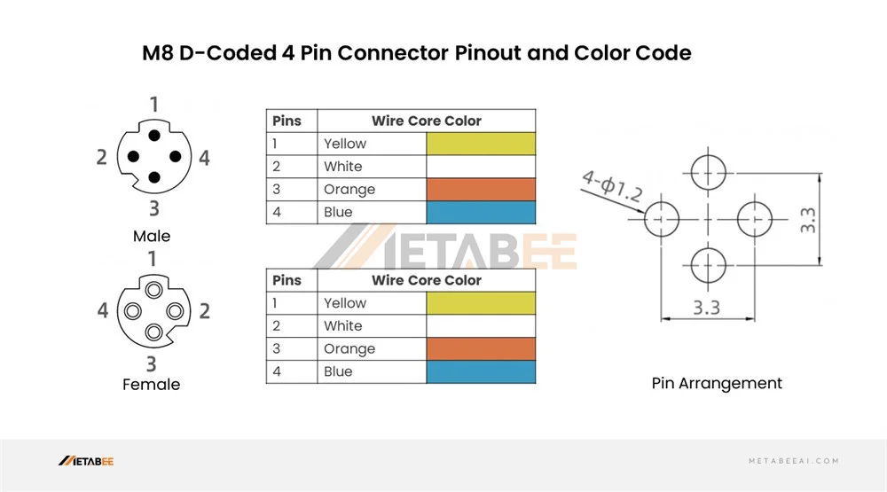
Pinout & Color Code Definition (Standard Ethernet Colors): Unlike standard sensor wire colors, D-Coded Ethernet cables follow data transmission color standards.
- Pin 1: Yellow (YE) – Transmit Data + (TX+)
- Pin 2: White (WH) – Receive Data + (RX+)
- Pin 3: Orange (OG) – Transmit Data – (TX-)
- Pin 4: Blue (BU) – Receive Data – (RX-)
Wiring Diagram Context: In a PROFINET or Ethernet wiring diagram, these four pins represent two twisted pairs. Proper shielding (connecting the cable shield to the connector knurl/housing) is mandatory in the wiring diagram to prevent Electromagnetic Interference (EMI) from disrupting the data packets.
Comparison: 4-Pin A-Coded vs. 4-Pin D-Coded
To avoid catastrophic wiring mistakes, refer to this quick comparison:
| Feature | M8 4-Pin A-Coded | M8 4-Pin D-Coded |
|---|---|---|
| Primary Application | Sensors, Actuators, I/O Blocks | Industrial Ethernet, PROFINET |
| Signal Type | DC Power, Analog/Digital I/O | High-Speed Data (100 Mbit/s) |
| Standard Color Code | Brown, White, Blue, Black | Yellow, White, Orange, Blue |
| Keying / Anti-Mating | Single standard keyway | Distinctive cross-shaped insert |
| Shielding Requirement | Optional (depends on noise) | Mandatory for data integrity |
M8 5-Pin Connector (B-Coded)
M8 B-Coded 5-Pin connectors are designed for Fieldbus applications.
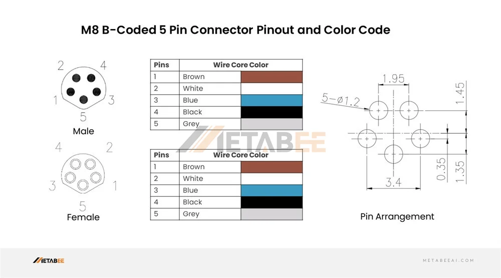
Pinout & Color Code Definition (Example for typical Fieldbus):
- Pin 1: Brown (BN) – Power supply for bus logic
- Pin 2: White (WH) – Bus Data Line A (Negative)
- Pin 3: Blue (BU) – Ground for bus logic
- Pin 4: Black (BK) – Bus Data Line B (Positive)
- Pin 5: Grey (GY) – Shield or Ground connection (depending on protocol)
Wiring Diagram Context: The wiring diagram for B-Coded connectors focuses on daisy-chaining devices along a bus network. Pin 2 and Pin 4 act as the differential data pair. Precise termination resistors are often required at the end of the wiring loop to prevent signal reflection.
High-Density Configurations: M8 6-Pin Connector
As devices shrink but demand more functionality, high-density M8 connectors come into play. The 6-pin A-Coded M8 connector is widely used in complex vision sensors, rotary encoders, and multi-channel measurement devices.
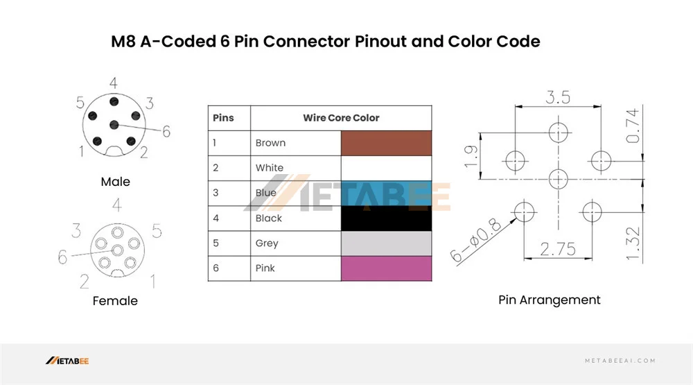
Pinout & Color Code Definition:
- Pin 1: Brown (BN)
- Pin 2: White (WH)
- Pin 3: Blue (BU)
- Pin 4: Black (BK)
- Pin 5: Grey (GY)
- Pin 6: Pink (PK)
Wiring Diagram Context: In a 6-pin wiring diagram, power and ground usually remain on Brown and Blue. The remaining four wires (White, Black, Grey, Pink) are utilized for multiple discrete outputs, alarm signals, or even RS-232 serial communication streams.
High-Density Configurations: M8 8-Pin Connector
The 8-pin M8 connector represents the pinnacle of miniaturization in industrial interconnects. Fitting 8 pins into an 8mm shell requires exceptional manufacturing precision, a standard rigorously maintained by Metabee.
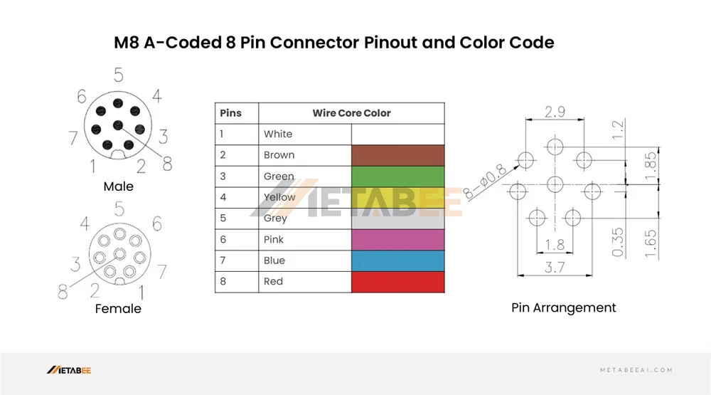
Pinout & Color Code Definition (DIN 47100 Standard): Because of the high pin count, the wire gauge (AWG) must be smaller (typically 26 AWG) to fit inside the cable jacket. The color code generally follows standard multi-core definitions:
- Pin 1: White (WH)
- Pin 2: Brown (BN)
- Pin 3: Green (GN)
- Pin 4: Yellow (YE)
- Pin 5: Grey (GY)
- Pin 6: Pink (PK)
- Pin 7: Blue (BU)
- Pin 8: Red (RD)
(Note: Always verify the specific manufacturer’s datasheet, as custom high-density pinouts can occasionally deviate from DIN 47100).
Wiring Diagram Context: The 8-pin wiring diagram is highly complex and is typically used for advanced absolute encoders, safety laser scanners, or transmitting Gigabit Ethernet (though M12 X-coded is more common for GigE). Because the pins are so close together, strict attention to shielding and twisted-pair routing in the wiring diagram is essential to prevent cross-talk.
How to Select the Right M8 Connector for Your Application
Choosing the correct M8 connector goes beyond just counting the pins. To ensure a robust connection that lasts the lifespan of your machine, you must consider the following factors:
Define Pin Count & Data Needs:
Are you transmitting simple power/switch signals (3-pin/4-pin A-coded), or do you need to pass Industrial Ethernet (4-pin D-Coded)? Don’t over-specify pins you don’t need, but ensure you have enough for diagnostic outputs.
Verify the Coding:
Double-check the receptacle on your device. An A-coded cable will physically not fit into a D-coded switch.
Determine the IP Rating Requirements:
For general factory automation, IP67 (temporary submersion) is sufficient. For food and beverage or washdown environments, look for IP68 or IP69K connectors that can withstand high-pressure, high-temperature jets.
Select the Right Cable Material (Jacket):
- PVC (Polyvinyl Chloride): Cost-effective, suitable for static installations with moderate mechanical stress.
- PUR (Polyurethane): Highly resistant to oil, abrasion, and chemicals. Ideal for drag chains (C-tracks) and continuous flexing applications in robotics.
- TPE (Thermoplastic Elastomer): Excellent for extreme temperatures and weld-slag resistance in automotive manufacturing.
Shielding Requirements:
If your wiring diagram involves analog signals, encoders, or Ethernet data, always opt for shielded M8 cables to protect against EMI/RFI noise from nearby motors or drives.
Related Products
- M8 Connectors
- M8 A-Coded 3-Pin Connectors
- M8 A-Coded 4-Pin Connectors
- M8 B-Coded 5-Pin Connectors
- M8 A-Coded 6-Pin Connectors
- M8 A-Coded 8-Pin Connectors
- M12 Connectors
- M5 Connectors
Conclusion & Choose Metabee for Your M8 Interconnect Solutions
Understanding the M8 connector pinout, decoding the color codes, and accurately applying them to your wiring diagrams are non-negotiable skills for modern industrial integration. Getting it right ensures seamless data flow, accurate sensor readings, and the overall stability of your automated architecture. Getting it wrong can result in blown I/O cards and hours of troubleshooting.
When failure is not an option, you need interconnect solutions you can trust.
Metabee is dedicated to engineering premium, high-reliability M8 connectors and custom wire harnesses tailored to your exact specifications. From standard 3-pin sensor cables to complex 8-pin shielded assemblies for robotics, our products meet rigorous IEC standards and undergo exhaustive quality testing.
Ready to upgrade your industrial connectivity? Contact the Metabee engineering team today for expert technical consultation, custom wiring diagram assistance, or to request high-quality product samples for your next automation project.
Frequently Asked Questions (FAQs)
Q1: What is the difference between a 4-Pin A-Coded and a 4-Pin D-Coded M8 connector?
A: A-Coded is for sensors, actuators, and DC power, while D-Coded is strictly for high-speed data transmission (up to 100 Mbit/s, like Industrial Ethernet). Their distinct physical keying prevents accidental mismating.
Q2: What is the standard color code for wiring a typical 4-pin M8 sensor connector?
A: Based on the IEC 61076-2-104 standard, the universal wiring colors are Pin 1 (Brown) for Positive Power (+24V DC), Pin 2 (White) for Secondary Signal (NC), Pin 3 (Blue) for Ground (0V), and Pin 4 (Black) for Primary Signal (NO).
Q3: Are 3-pin and 4-pin M8 connectors physically intermateable?
A: No, they are completely incompatible due to different pin spacing and layouts. Attempting to force them together will permanently damage the pins and the insulator. You must always match the exact pin count.
Q4: What wire gauge (AWG) is suitable for high-density 6-pin and 8-pin M8 connectors?
A: Due to limited pin spacing, these high-density configurations require smaller wire sizes, most commonly 26 AWG. To avoid tedious micro-soldering, relying on pre-assembled, overmolded M8 cables from Metabee is highly recommended.
Q5: How do I choose between PVC and PUR cable jackets for my M8 wiring?
A: Choose PVC for standard, static indoor environments as a cost-effective solution. Choose PUR for harsh industrial conditions requiring resistance to oil, chemicals, and continuous flexing (such as robotic arms or drag chains).
