
Welcome to the ultimate D38999 Connector Guide. Navigating the complex world of military-specification circular connectors is essential for success in high-reliability engineering and procurement. This comprehensive technical guide aims to eliminate confusion by systematically breaking down the core structural elements of the D38999 connector family. We will provide a detailed comparison of the four distinct D38999 Series (I, II, III, IV). This comparison will focus on their crucial differences in coupling mechanisms (Bayonet, Triple-Start Threaded, and Breech-Lock) and physical profiles. Furthermore, we will explain the most common shell styles (such as Wall Mount Flange and Jam Nut) and shell sizes, and introduce the critical concept of Insert Arrangements, ensuring you can make informed selection decisions from the very first step.
Introduction
Before diving into the technical variations, it is crucial to establish the correct terminology and history of the standard.
What is D38999? Decoding the Nomenclature
The D38999 connector is a high-performance, circular electrical connector designed specifically for severe duty environments where reliability cannot be compromised. Its primary features include rear-release, removable crimp contacts, polarization keys to prevent mis-mating, and an integrated sealing system for environmental protection.
The Standard: The currently governing document is MIL-DTL-38999. MIL stands for Military, indicating that this connector type conforms to strict defense requirements. The “DTL” stands for Detail Specification, confirming that this is the technical manual detailing every requirement for design, manufacturing, and testing.
D38999 vs MIL-C-38999 vs MIL-STD-38999
Clarifying Legacy and Common Terms:
- MIL-C-38999: This is the older, superseded designation for the standard. The “C” stood for Connector. While the specification has evolved, many in the industry still use “MIL-C-38999” colloquially, especially when referring to legacy systems.
- D38999: This is the universal, common industry shorthand. It simply refers to any connector built to the dimensional and performance standards of MIL-DTL-38999.
- MIL-STD-38999: This term is technically incorrect. While MIL-STDs define procedures and common requirements, the actual product specification is always designated as a MIL-DTL (Detail).
Understanding this nomenclature ensures clear communication across supply chains and engineering teams.
Historical Evolution of the MIL-DTL-38999 Standard
The D38999 specification is the culmination of decades of development in high-reliability interconnect technology, evolving to meet increasingly demanding military and aerospace requirements.
- 1950s – Early Precursors: Earlier military specifications, such as MIL-C-5015, established the fundamental need for rugged circular connectors in defense applications.
- 1960s – Foundation Laid: Predecessor specifications, including MIL-C-26482 and MIL-C-83723, introduced foundational concepts like rear-release contacts, robust environmental sealing, and keying/polarization. These concepts directly influenced the D38999 design.
- Late 1960s/Early 1970s – The MIL-C-38999 Birth: The original MIL-C-38999 specification is formally introduced. This specification standardized four distinct series (I, II, III, IV), each offering a different approach to coupling (Bayonet, Threaded, Breech-Lock) and physical profile.
- Evolution (Series III Focus): Series III features a Triple-Start Threaded coupling and superior EMI shielding. This design quickly emerges as the most robust variant, specifically engineered to counter extreme vibration and temperature issues prevalent in modern aerospace and defense platforms.
- Present Day – MIL-DTL-38999: The governing document transitions to MIL-DTL-38999 (Detail Specification). This reflects the continued standardization, refinement of performance requirements, and guaranteed interoperability across all qualified manufacturers globally.
Essential Design Features of D38999
The D38999 family is defined by a set of core design principles that ensure its reliability in extreme conditions. These features are standardized across nearly all series and manufacturers:
- Rear-Release, Removable Crimp Contacts: This allows for simplified field maintenance and repair. Contacts are crimped onto the wire and inserted or removed from the rear of the connector insulator using specialized tools, without requiring disassembly of the main shell.
- Integrated Environmental Sealing: Internal features, including grommets and interfacial seals, provide superior protection against moisture, hydraulic fluids, and dust ingress, meeting stringent IP standards.
- Superior EMI/RFI Shielding: The metal shell construction, combined with conductive finishes and robust shell-to-shell grounding, provides comprehensive protection. This system ensures continuous 360-degree shielding against electromagnetic and radio-frequency interference.
- Polarization and Keying: A primary keyway and multiple secondary keying positions prevent connector mis-mating or damage by ensuring only correctly oriented plugs and receptacles can be fully coupled.
- High-Vibration Performance: Especially in Series III, the design is engineered to maintain low contact resistance and stable electrical continuity even under sustained, extreme mechanical vibration profiles.
Why MIL-DTL-38999 is the Gold Standard
In the demanding worlds of aerospace, defense, and high-reliability industrial applications, components must perform flawlessly under extraordinary stress. When it comes to electrical interconnects, few products command the respect and reliance that the MIL-DTL-38999 family of circular connectors does. D38999 connectors are popular for their ruggedness, exceptional environmental sealing, and superior performance against vibration, temperature extremes, and electromagnetic interference (EMI/RFI). So, they are widely regarded as the undisputed gold standard in the industry.
The D38999 specification is famous for its sheer complexity, featuring four distinct series (I, II, III, IV) and a multitude of shell styles. However, this complexity can be a significant hurdle for new engineers and even seasoned procurement specialists. Confusing the series or selecting the wrong shell style can lead to sourcing errors, installation failure, and ultimately, system unreliability. So, understanding the core foundational differences is the first critical step toward flawless component selection.
Decoding the D38999 Series (I, II, III, IV)
The 4 series of D38999 are not just arbitrary variations; they represent distinct design approaches, primarily differentiating themselves by their coupling mechanism and their physical profiles.
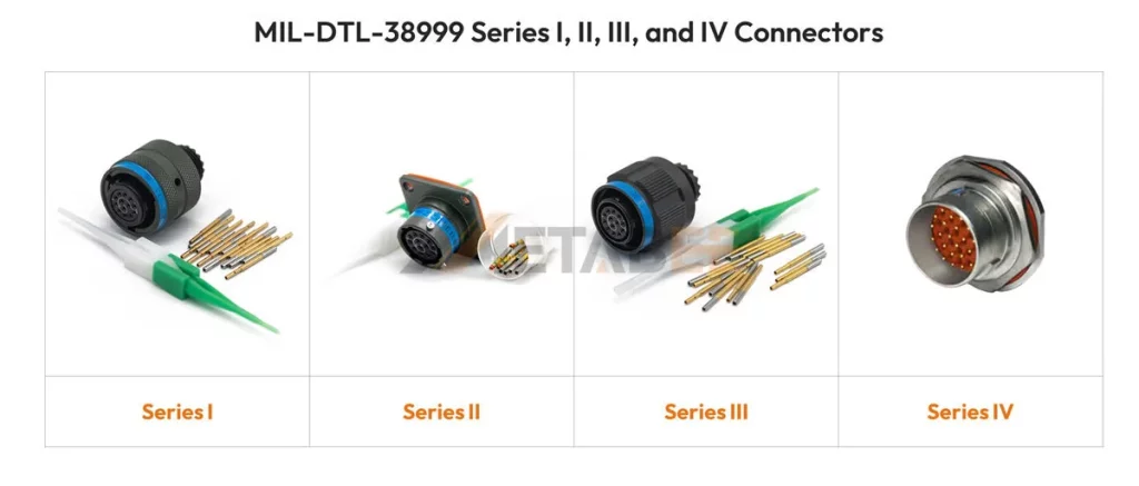
Series I (Latching/Bayonet)
Series I connectors represent one of the earlier iterations of the D38999 family. They utilize a three-point Bayonet coupling mechanism.
Coupling Mechanism: Bayonet
The plug locks onto the receptacle via three locking pins that mate with slots in the receptacle shell. A simple twist and click secure the connection.
Key Features
Its main benefit is quick disconnect/mating. This bayonet mechanism allows for rapid assembly and disassembly without the need for extensive rotations. The contacts are rear-removable, and the connectors offers good environmental sealing.
Physical Profile
Series I tends to be physically larger than Series III and Series II designs, making it less suitable for space-constrained applications.
Current Usage
These components are generally less common in new, cutting-edge designs because the Series III offers superior performance in high-vibration environments. However, they still remain specified for interchangeability with older systems. If you are servicing equipment originally designed in the 1970s or 80s, you are likely dealing with Series I.
Part Number
Series I part numbers begin with the ‘MS’ prefix and consist of seven types, specifically: MS27467, MS27466, MS27656, MS27496, MS27505, and MS27901. Detailed information is shown in the figure below:
- 27467 – Plug (T-type only)
- 27466 – Front-mounted wall-type flange receptacle (T-type only)
- 27656 – Rear-mounted wall-type flange receptacle (T-type only)
- 27496 – Front-mounted box-type flange receptacle (E-type only)
- 27505 – Rear-mounted box-type flange receptacle (E-type only)
- 27468 – Jam nut receptacle (T-type only)
- 27901 – Circular adapter receptacle (T-type only)
Additional details are available in the METABEE MIL-DTL-38999 Catalog.
Series II (Low-Profile Bayonet)
Series II was developed specifically to address space and weight limitations, making it the slimmest and lightest option in the D38999 family.
Coupling Mechanism
Like Series I, it uses a Bayonet coupling mechanism, providing quick connection.
Key Features
The defining characteristic is its low-profile design. Series II connectors are significantly smaller, lighter, and feature a reduced shell-to-shell spacing compared to the other series. This makes them invaluable when designing systems where every millimeter and gram counts.
Trade-off: Robustness vs. Size
The compact design necessitates certain trade-offs. Series II offers lower resistance to extreme vibration and less potent EMI shielding compared to the threaded Series III. Crucially, Series II is not scoop-proof. This means that if the plug is accidentally jammed or “scooped” into the receptacle at an angle, the exposed contacts can be easily damaged, leading to circuit failure.
Ideal Application
These components are best used in benign or space-limited environments where weight reduction is prioritized over extreme mechanical robustness. Examples include applications inside fixed-wing aircraft cabins or small unmanned aerial systems (UAS).
Part Number
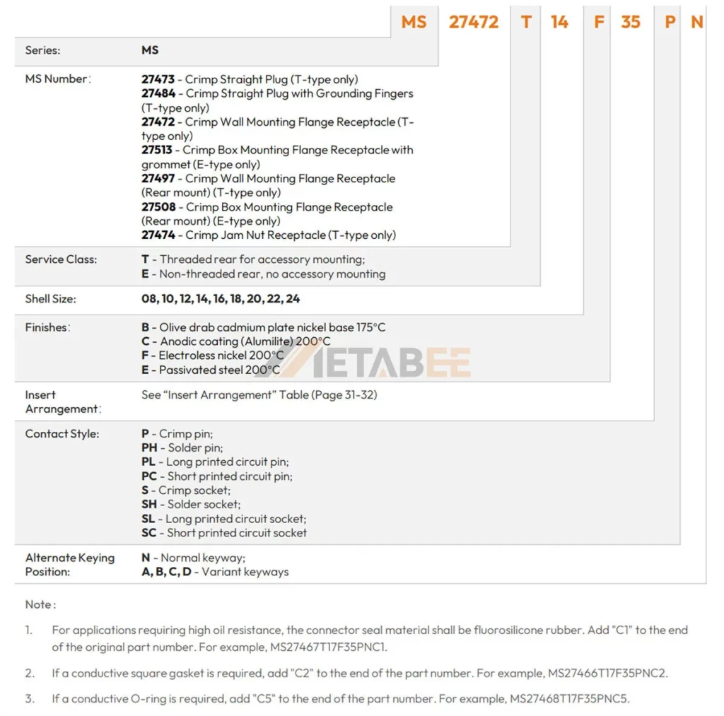
Similar to Series I, Series II part numbers also begin with the ‘MS’ prefix. There are seven specific types: MS27473, MS27484, MS27472, MS27513, MS27497, MS27508, and MS27474.
- 27473 – Crimp Straight Plug (T-type only)
- 27484 – Crimp Straight Plug with Grounding Fingers (T-type only)
- 27472 – Crimp Wall Mounting Flange Receptacle (Ttype only)
- 27513 – Crimp Box Mounting Flange Receptacle with grommet (E-type only)
- 27497 – Crimp Wall Mounting Flange Receptacle (Rear mount) (T-type only)
- 27508 – Crimp Box Mounting Flange Receptacle (Rear mount) (E-type only)
- 27474 – Crimp Jam Nut Receptacle (T-type only)
Additional details are available in the METABEE MIL-DTL-38999 Catalog.
Series III (Triple-Start Threaded) – The Modern Workhorse
Series III is, without a doubt, the industry standard for almost all modern, high-reliability applications and new designs. In short, it is the pinnacle of the D38999 specification.
Coupling Mechanism
D38999 series III connectors feature a Triple-Start Threaded Coupling. This design requires just a single 360-degree turn to fully mate and secure the connection, providing rapid, secure locking.
Key Features
- Superior Vibration Resistance: The threaded coupling, combined with a positive shell-to-shell bottoming feature, ensures the connection remains robust and stable. This reliability is maintained even under extreme vibration profiles, which is a critical requirement for platforms such as fighter jets and rocket stages.
- Superior EMI Shielding: The continuous metal contact between the shells provides excellent 360-degree shielding against electromagnetic interference.
- Crucial Benefit: Scoop-Proof Design: This is the most significant safety advantage. The design recesses the contacts deep within the insulator, ensuring that the plug shell acts as a shield. If the plug is forced into the receptacle, the metal shells hit each other before the contacts touch, protecting the fragile pin contacts from bending or damage.
Adoption
Due to its unmatched performance in harsh environments, Series III is the default choice for military electronics, commercial avionics, and heavy industrial machinery.
Part Numbers
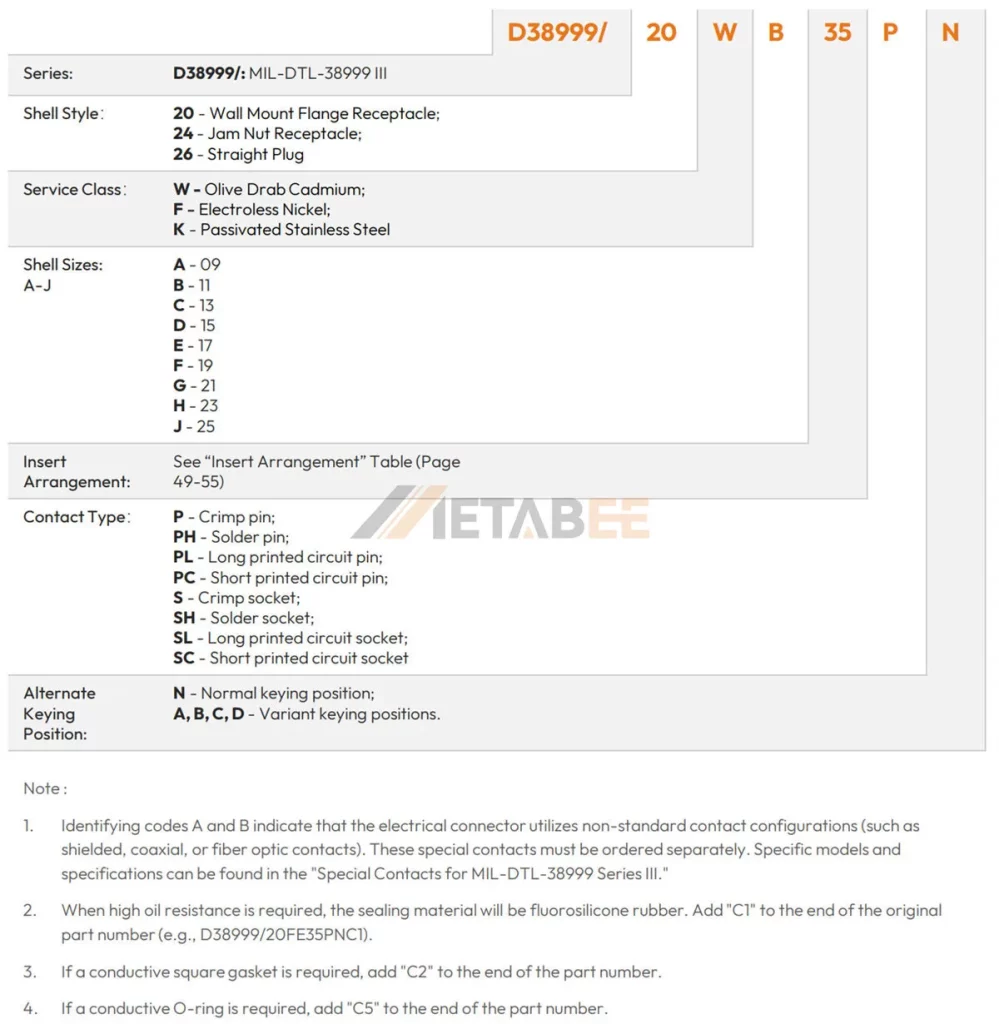
Series III, the most widely procured series today, uses the slash sheet designators /20 (for wall mount flange receptacle), /24 (for jam nut receptacle), and /26 (for straight plug). These identifiers specifically denote the robust, threaded coupling mechanism.
- 20 – Wall Mount Flange Receptacle
- 24 – Jam Nut Receptacle
- 26 – Straight Plug
Additional details are available in the METABEE MIL-DTL-38999 Catalog.
Series IV (Breech-Lock)
Series IV is the least common but highly specialized member of the family, designed for ultra-rapid connect/disconnect scenarios.
Coupling Mechanism
Breech-Lock Quick Disconnect. Unlike the rotational action of the other series, Series IV uses a push-pull locking mechanism that requires almost no rotation.
Key Features
Offers the fastest mating option within the D38999 specification. The mechanism locks with three equally spaced locking pins, similar to a breech-loading firearm, offering high mechanical strength once mated.
Environmental Protection
Series IV maintains the high sealing and environmental integrity expected of the D38999 family.
Current Usage
Its usage is highly specialized. It is often employed in applications requiring immediate breakaways or rapid replacement of sensor arrays and critical modules. This is necessary for platforms such as specialized ground vehicles or certain test and measurement equipment, where time is critical.
Part Number
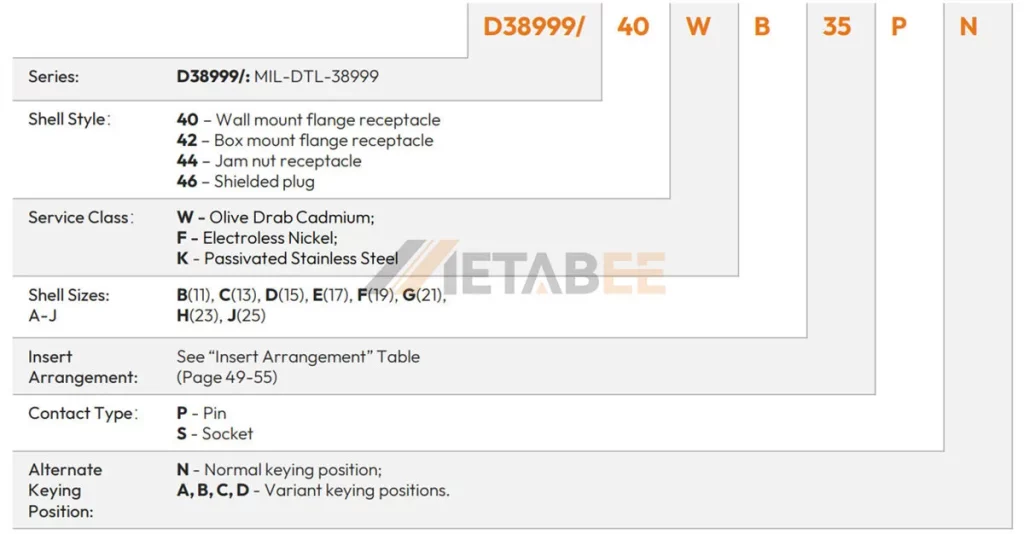
The specialized Series IV is identified by the slash sheets /40, /42, /44, and /46. These unique codes are necessary due to the distinctive breech-lock coupling mechanism.
- 40 – Wall mountflange receptacle
- 42 – Box mount flange receptacle
- 44 – Jam nut receptacle
- 46 – Shielded plug
Additional details are available in the METABEE MIL-DTL-38999 Catalog.
Series Comparison Overview
Choosing the correct D38999 series hinges on balancing the requirements for vibration resistance, mechanical profile (size/weight), and coupling speed. The table below summarizes the core differences between the four established series:
| D38999 | Coupling | Scoop Proof | Durability | High Impact Schock | Bend Moment | Price |
|---|---|---|---|---|---|---|
| Series l | Standard Bayonet | Yes | 500 | Yes | 650 Ibs in | $ |
| Series II | Low-Profile Bayonet | No | 250 | No | 150 Ibs in | $ |
| Series III | Triple Start Threded | Yes | 500 | Yes | 1000 Ibs in | $$ |
| Series IV | Breach-Lok | Yes | 500 | Yes-Heavy | 1000 Ibs in | $$$ |
Essential D38999 Shell Styles and Sizes
Once the connector series is chosen (which is often Series III for new designs), the next crucial step is selecting the correct shell style and size. These dimensions dictate two critical aspects: how the connector interacts with the cable and how it interfaces with the mounting panel.
The following information is described using D38999 Series III part numbers. For part numbers corresponding to other series, please consult the METABEE MIL-DTL-38999 Catalog.
Plugs (Cable-Mounted Connectors)
Plugs are the mobile half of the connector pair, typically mounted on the cable assembly.
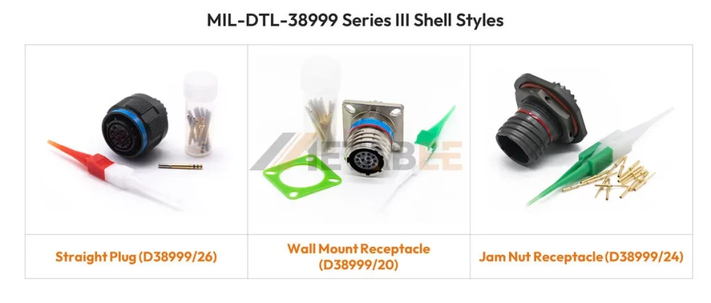
Straight Plug (D38999/26): This is the quintessential connector form factor. The cable exit is straight (axial) relative to the connector body. It is used in the vast majority of cable-to-equipment or cable-to-cable connections where space constraints are not an issue.
Receptacles (Equipment-Mounted Connectors)
Receptacles are the stationary half, designed to be mounted onto a piece of equipment, a panel, or a bulkhead.
Wall Mount Receptacle (Square Flange) (D38999/20):
- Function: This style mounts to a panel or box via a square flange with four mounting holes.
- Benefit: It provides maximum stability, torque resistance, and a reliable panel seal. It is ideal when the connector is expected to withstand high coupling forces or when maximum mechanical rigidity is needed.
Jam Nut Receptacle (D38999/24):
- Function: The jam nut receptacle mounts through a single circular cutout in the panel. It is secured from the rear using a large internal nut, which “jams” the receptacle into place.
- Benefit: This method significantly simplifies and speeds up installation and replacement in the field, as only one hole needs to be cut and the nut is easily tightened. It is frequently specified for equipment that requires frequent servicing or quick manufacturing turnaround.
Shell Size: Determining Connector Diameter and Capacity
Beyond the coupling mechanism (Series) and the mounting style (Plugs/Receptacles), the Shell Size is the final dimensional specification required to define the connector body.
What Shell Size Indicates
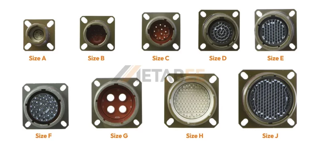
The Shell Size for D38999 Series III is represented by a single letter: A, B, C, D, E, F, G, H, J. D38999 connectors typically range from the smallest shell size, 9, up to the largest common size, 25.
- A – 09
- B – 11
- C – 13
- D – 15
- E – 17
- F – 19
- G – 21
- H – 23
- J – 25
The shell size determines the maximum capacity—the total number and size of electrical contacts the connector can physically hold.
Interdependence
Shell size is intrinsically tied to the insert arrangement. A specific insert arrangement pattern (e.g., E-21) can only fit into its designated shell size (e.g., size 17). Getting the size wrong means the two halves simply will not mate.
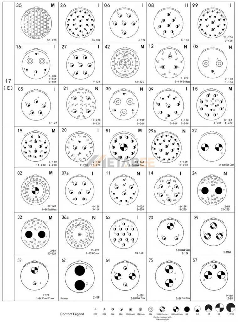
The Crucial Detail: D38999 Insert Arrangements
While the series and shell style define the mechanical envelope of the connector, the Insert Arrangement defines its electrical heart—the wiring schematic, pin-out, and current capacity.
What is an Insert Arrangement?
The insert arrangement is the precise pattern, density, and size of the electrical contacts molded into the insulating dielectric material (the insert). It dictates the electrical function and defines the number of circuits the connector can handle.
Nomenclature
The designation for the insert arrangement varies slightly based on the connector series:
Series I and II: The arrangement is designated by 2 numbers separated by a hyphen (e.g., 10-05).
- The first number (11) represents the Shell Size.
- The second number (05) is the specific Arrangement Pattern Code, referring to the unique layout of contacts within that shell size.
Series III and IV: The arrangement is sometimes designated using a character (letter) and a number separated by a hyphen (e.g., D–38).
- The character (D) represents the Shell Size code.
- The number (38) is the specific Arrangement Pattern Code, referring to the unique layout of contacts within that shell size.
Full Catalog Reference for 4 Series
It is important to note that insert arrangements are not universally interchangeable across all four D38999 series. While many common arrangements are shared, some specific high-density or special-purpose patterns are unique to Series I, II, or IV due to their different back-end dimensions or coupling hardware.
To ensure absolute compatibility and dimensional accuracy, always consult a verified catalog. The Metabee D38999 Connector Catalog provides a comprehensive, verified list of all available insert arrangements for all D38999 series.
Main Manufacturers
The D38999 standard was established and historically dominated by major Western manufacturers, often referred to as Qualified Product List (QPL) suppliers for military contracts. These key industry players include:
Introducing High-Value Alternatives: Metabee D38999 Connectors
While the legacy QPL manufacturers are known, the global connector market has matured, allowing for high-quality, high-cost-performance alternatives to emerge.
We proudly introduce Metabee as a well-known Chinese manufacturer specializing in high-quality, D38999-compliant circular connectors. Metabee offers components that strictly adhere to the MIL-DTL-38999 standard. So, these components provide the same high reliability, environmental sealing, and mechanical robustness demanded by the industry.
Metabee’s Value Proposition:
- High Reliability, High Cost-Performance: Metabee delivers products that meet or exceed industry performance expectations but at a more competitive price point. This makes Metabee an ideal choice for commercial aerospace, industrial automation, ruggedized communication, and other high-reliability applications where budget constraints are tighter than in strict military programs.
- Full Adherence to Standard: Metabee connectors are designed for full form, fit, and function interchangeability with components from other manufacturers, simplifying the cross-reference process.
- Global Supply Chain Resilience: Partnering with Metabee provides procurement teams with a diversified, resilient sourcing option, mitigating risks associated with single-source supply chain bottlenecks often found with traditional QPL suppliers.
Choosing Metabee means securing the D38999 performance you need without incurring unnecessary cost penalties, ensuring your project remains on budget and on schedule.
Conclusion
This guide was designed to demystify the critical first steps in D38999 connector selection by detailing the four primary series and the most common shell styles.
We learned that Series III (Triple-Start Threaded) stands out as the industry workhorse, offering unparalleled vibration resistance and the essential scoop-proof design required for the harshest environments. While Series II (Low-Profile Bayonet) provides a weight and space advantage for less demanding applications, and Series I and IV offer specialized coupling, Series III remains the default for new high-reliability designs. Furthermore, the choice between Jam Nut (for ease of installation) and Wall Mount Flange (for maximum stability) dictates the mechanical interface with your equipment.
As a high-value supplier of D38999 compliant connectors, Metabee offers reliable, cross-reference interchangeable solutions across all four D38999 Series (I, II, III, and IV), covering all standard shell styles and a vast range of insert arrangements. We provide the full spectrum of high-performance connectors, ensuring you don’t have to compromise reliability for cost.
If you have technical questions regarding insert arrangements, contact sizing, or require a competitive quote for any type of D38999 connector, please contact our technical sales team today.
Related Products
- MIL-DTL-38999 (D38999) Connectors
- MIL-DTL-5015 (MS5015) Connectors
- MIL-DTL-26482 Connectors
- J30J Connectors
Frequently Asked Questions (FAQs)
Q: What is the difference between MIL-DTL-38999, MIL-C-38999, and D38999?
A: MIL-DTL-38999 is the current, governing specification document (Detail Specification). MIL-C-38999 is the older, superseded designation. D38999 is the common industry shorthand used to refer to any connector built to the dimensional and performance standards of the specification family.
Q: Which D38999 series is recommended for modern, high-vibration environments, and why?
A: Series III (Triple-Start Threaded) is the industry standard and preferred choice for new designs in harsh environments. Its threaded coupling and positive shell-to-shell bottoming provide superior vibration resistance and excellent EMI shielding.
Q: What is the “Scoop-Proof” design, and which series offer this protection?
A: Scoop-Proof means the connector is designed to protect the fragile pin contacts. The plug shell acts as a shield, recessing the contacts so the metal shells hit each other before the contacts touch if the plug is accidentally jammed. Series III and Series IV both offer the Scoop-Proof design.
Q: What is the main trade-off when selecting D38999 Series II?
A: Series II is the smallest and lightest (low-profile) option, which is ideal for space-constrained applications. However, the trade-off is lower resistance to extreme vibration and it is not scoop-proof, meaning contacts are vulnerable to damage during mis-mating.
Q: How do Bayonet coupling and Triple-Start Threaded coupling differ functionally?
A: Bayonet coupling (used in Series I and II) provides quick disconnect/mating via a simple twist and click. Triple-Start Threaded coupling (used in Series III) requires a single 360-degree rotation for secure mating, offering significantly higher mechanical stability and vibration resistance.
Q: What do the two most common receptacle styles, Wall Mount and Jam Nut, dictate?
A: They dictate how the connector attaches to the panel or equipment. Wall Mount Receptacles use a square flange and four mounting holes for maximum stability. Jam Nut Receptacles mount through a single circular cutout and are secured by an internal nut, offering faster, easier installation and replacement.
Q: What information is defined by the D38999 “Insert Arrangement”?
A: The Insert Arrangement defines the electrical heart of the connector. It specifies the precise pattern, density, total number, and size of the electrical contacts within the insulating material (insert). This dictates the connector’s electrical function and capacity.
Q: Are D38999 connectors from different manufacturers, like Amphenol or Metabee, interchangeable?
A: Yes. Because MIL-DTL-38999 is a military specification, all products manufactured to this standard must be dimensionally and functionally interchangeable. This means components from different compliant suppliers can be confidently cross-referenced.
Q: What is the value proposition of choosing Metabee Connectors?
A: Metabee is introduced as a Chinese manufacturer offering high-quality, fully MIL-DTL-38999 compliant connectors. Their value proposition is high reliability at a high cost-performance advantage, providing a resilient and budget-competitive alternative to traditional Qualified Product List (QPL) suppliers.