In the world of modern RF and microwave engineering, precise control over signal levels is paramount to ensuring optimal performance and protecting sensitive components. The RF attenuator is a fundamental and indispensable passive device that enables this control. This guide provides a comprehensive reference to RF attenuators, including their definition, types, working principles, key specifications, applications, and guidance on selecting the right device for your system.
What is an RF Attenuator?
In this section, we explain what an RF attenuator is and why it is essential in RF engineering.
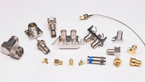
Metabee RF Attenuators
Definition
An RF Attenuator is a two-port passive electronic device designed to reduce (attenuate) the power or amplitude of an RF signal. It does not distort its waveform or affect its frequency. Moreover, it acts as a controlled “buffer” between a source and a load, providing a known and precise amount of signal loss (attenuation value), measured in decibels (dB).
Core Functions
The main functions of an RF attenuator include
- Signal Level Adjustment: Reducing a signal to a desired, manageable level for other components.
- Impedance Matching: A well-designed attenuator can improve the impedance match between a source and a load, often by masking poor Voltage Standing Wave Ratio (VSWR) conditions.
- Isolation and Buffering: Providing a degree of isolation between different stages of a circuit, preventing reflected power from damaging the source or causing instability.
- Calibration and signal chain leveling: In measurement systems, attenuators can be used to step down known amounts of signal to calibrate instruments or simulate different scenarios.
- Protection: Shielding sensitive measurement equipment or active components from excessively high-power signals.
Types of RF Attenuators
RF attenuators come in various types to meet different application requirements. So we can divide them into 2 categories primarily based on the connector interface and the ability to adjust the attenuation level.
By Control Method
The most fundamental way to categorize attenuators is by how their attenuation value is controlled.
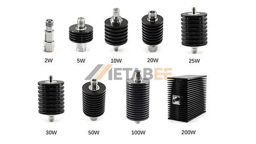
Fixed Attenuators
Fixed Attenuators provide a permanent, non-adjustable reduction in signal power, specified by a single value. The constant decibel (dB) value (e.g., 3 dB, 10 dB, 20 dB). They are constructed using specific resistive networks, typically in a π (pi) or T configuration, and are chosen for permanent installations where a constant level of attenuation is required. Their advantages include simple design, high reliability, low cost, and excellent repeatability.
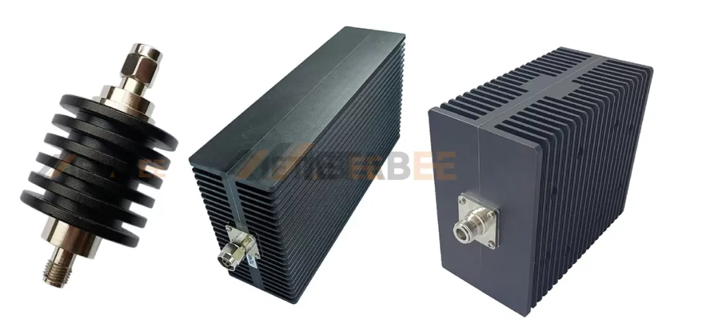
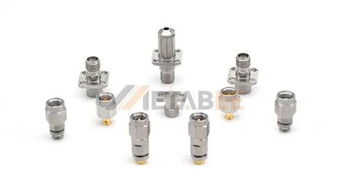
RF Fixed Attenuators
Step Attenuators
Step attenuators (also often referred to as digital step attenuators or switched attenuators) are a specialized type of variable attenuator. They allow the attenuation to be changed in discrete, fixed steps (e.g., 0 dB, 1 dB, 2 dB, 4 dB, 8 dB) via switches or digital controls. So step attenuators provide a compromise between a fixed attenuator and a variable attenuator, offering high precision along with adjustability.
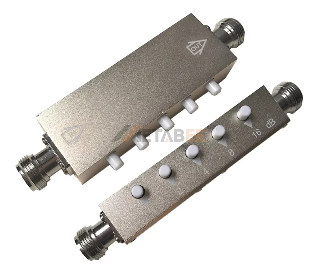
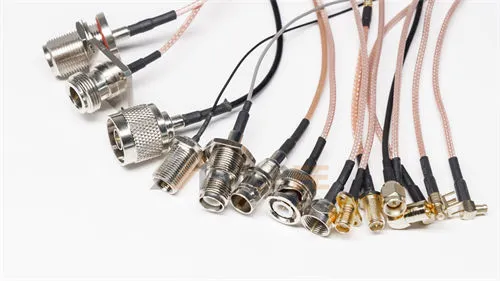
RF Step attenuators
Variable Attenuators
Variable attenuators allow the attenuation level to be changed either manually (mechanical knob, slider) or electronically (voltage-controlled, digital interface) over a defined range. SThey are well-suited for adaptive systems, calibration benches, and environments where the signal level may vary.
By Connector Interface
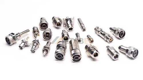
Attenuators are often named after the specific RF connector used on their input and output ports. Thus, it determines compatibility within the larger RF system.
Metabee offers a comprehensive range of high-performance RF fixed and variable attenuators.
Below are some of the most common types:
Key Electrical Specifications
Key technical specifications for the RF attenuator include:
| Operating frequency | DC – 8 GHz |
| Impedance | 50 Ohm |
| Attenuation | 1DB, 2DB, 3DB, 5DB, 6DB, 10DB, 15DB, 20DB, 30DB, 40DB, 50DB, 60DB, 90DB |
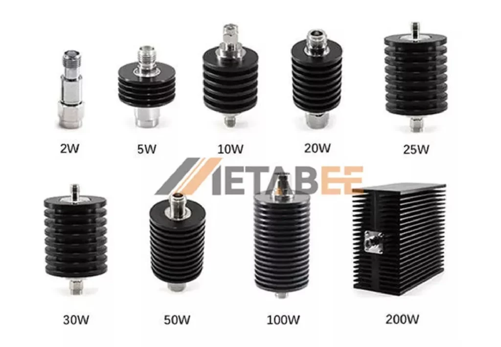
| Power | 2W, 5W, 10W, 15W, 25W, 30W, 50W, 100W, 150W, 200W, 300W, 500W |
| VSWR | ≤1.2 |
| IP Rating | IP20 |
| Operating Temperature | -55°C to +125°C |
How Does an RF Attenuator Work?
In this part, we explain how attenuation is produced, how the internal circuitry works, and what components make up the device.
What is RF Attenuation?
- Definition: Attenuation is the reduction in power of a signal as it passes through a component.
- Unit: Attenuation is measured in decibels (dB).
- Formula (Power Ratio):

Where Pin is the input power and Pout is the output power. A higher dB value indicates a greater reduction in signal power.
For example, A 10 dB attenuator, for example, reduces the signal power by a factor of 10.
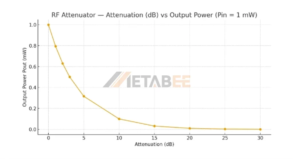
Signal Attenuation Curve
Working Principle
The basic principle behind an RF attenuator’s operation is the dissipation of excess signal energy as heat.
- Energy Absorption: When an RF signal enters the attenuator, it encounters precisely designed internal resistive elements (resistors).
- Power Conversion: These resistive elements absorb a specific portion of the signal’s electrical energy and convert it into thermal energy (heat). Therefore, this conversion is essential for reducing the signal amplitude.
- Signal Output: The remaining signal, now reduced to the desired power level, is output from the attenuator.
Construction of RF Attenuators
Main construction elements include:
- Resistive Network: A combination of precision resistors configured in specific topologies (T-type, π-type).
- Connectors: Standard RF connectors such as SMA, BNC, N-type, or DIN are used for easy integration into test and measurement setups.
- Housing: A metal enclosure, typically made of brass or stainless steel with nickel or gold plating, to provide shielding and durability.
- Thermal Sink: For high-power attenuators, heat sinks or thermally conductive substrates are included to dissipate excess heat.
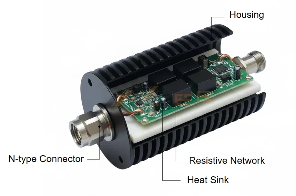
RF Attenuators Structure
RF Attenuator Circuit
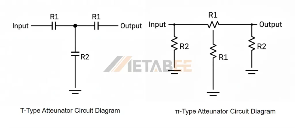
The two most common and fundamental circuit topologies for RF attenuators are the π network and the T network.
- T-type Attenuator: Consists of two series resistors and one shunt resistor forming a “T” shape. Additionally, it provides excellent impedance matching.
- π-type Attenuator: Features two shunt resistors and one series resistor arranged in a “π” configuration. It provides low insertion loss.
| Network | Configuration | Characteristics |
| T-Network | Series-shunt-series arrangement of three resistors. | Often preferred for fixed attenuators; uses two series resistors (R1) and one shunt resistor (R2). |
| Π-Network | Shunt-series-shunt arrangement of three resistors. | Also commonly used;uses two shunt resistors (Ra) and one series resistor (Rb). |
Basic attenuator topologies:
Applications
RF attenuators are vital components in a wide array of industries and applications, including:
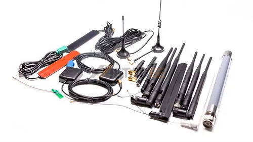
- Telecommunications: Employed in cellular infrastructure, Wi-Fi, and satellite communications to balance signal paths and manage gain.
- Test and Measurement: Used extensively in lab setups to adjust signal levels to prevent overloading sensitive test equipment like oscilloscopes, spectrum analyzers, and power meters.
- Radar Systems: Used to calibrate receiver sensitivity and provide level control precisely.
- Aerospace and Defense: Essential for testing, controlling, and ensuring the reliability of high-frequency military communication and electronic warfare systems.
- Broadcasting and CATV: Used to adjust signal levels for distribution networks, ensuring consistent signal strength at the end-user.
- Laboratory research: For precision control of RF signal paths.
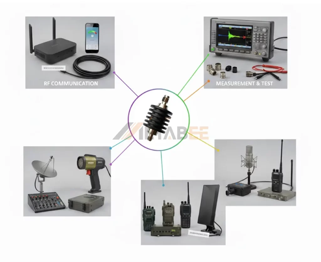
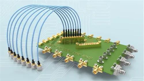
RF attenuators Applications
How to Select the Right RF Attenuator
To choose the appropriate RF attenuator for the application, we need a systematic evaluation of the following criteria:
Attenuation Value
Determine the required power reduction in dB. This is usually calculated based on the difference between the source power and the maximum allowable input power of the next component.
Frequency Range
Ensure the attenuator’s specified frequency range covers all operating frequencies of your system with sufficient margin. Usually, performance degrades at the edges of the specified band..
Power Rating
Select an attenuator with a power rating (Watts) significantly higher than the maximum expected input power. Over-specifying the power rating is a key protective measure.
Impedance
Standard RF attenuators come in 50-ohm and 75-ohm versions. Please verify that the attenuator’s characteristic impedance matches the system’s characteristic impedance.
VSWR
Prioritize attenuators with a low VSWR specification (e.g., $1.2:1$ or better) to minimize signal reflections and power loss.
Accuracy/Flatness
Evaluate the attenuation accuracy (deviation from nominal) and frequency flatness (variation of attenuation across the band). High-precision systems (test equipment, calibration, and measurement) require tighter tolerances.
Connector Type
Match the connector type (e.g., SMA, BNC, N-Type, DIN) and gender (male/female) to your system’s cables and components.
The Leading RF Attenuator Factories and Manufacturers
Here are some prominent RF attenuator manufacturers known for precision and reliability:
- Amphenol RF is well-established in RF and microwave component manufacturing, supplying attenuators among other RF connectivity products.
- Pasternack is a vendor focused on RF/microwave components, including attenuators. They have strong documentation and a broadband product range.
- Metabee is an emerging and famous manufacturer. Its RF attenuator lines have potential for competitive pricing and differentiation in your foreign-trade procurement context.
- Renhotec is a very powerful manufacturer of RF passive devices. Their products, including attenuators, present another supply chain option for global distribution.
Conclusion
RF attenuators are vital for controlling signal power in RF and microwave systems. They protect sensitive equipment, maintain signal integrity, and improve measurement accuracy without distorting the waveform. Discover what an RF attenuator is, how it works, and how to choose the right one for precise signal control and reliable RF system performance. In summary, an RF attenuator is more than a signal reducer. It is even a precision tool that safeguards components, optimizes system efficiency, and ensures long-term reliability.
Related Products
- RF Attenuators
- SMA Attenuators
- BNC Attenuators
- N-type Attenuators
- DIN Attenuators
- RF Variable Attenuators
Frequently Asked Questions (FAQ)
Q1: What is the primary function of an RF Attenuator?
A: The primary function of an RF attenuator is to reduce the power or amplitude of an RF signal by a precise, calibrated amount. They act as “power pads” in an RF system.
Q2: How does attenuation differ from signal loss?
A: Attenuation is the intentional, controlled reduction of a signal’s power for a specific system design purpose. Signal loss is often the unintended, undesirable reduction of signal power due to imperfections in the system. Attenuators introduce a calculated, deliberate loss.
Q3: What is the difference between a Fixed Attenuator and a Variable Attenuator?
A: The primary difference is their ability to change the level of signal reduction (attenuation):
- Fixed Attenuators provide a single, non-adjustable attenuation value (e.g., 10 dB). They are suitable for applications for a constant signal reduction.
- Variable Attenuators allow the attenuation value to be adjusted. These include continuously variable types (for fine-tuning) and Step Attenuators (which switch between discrete, fixed values, e.g., 1 dB, 2 dB, 3 dB).
Q4: What is the difference between an Attenuator and an Amplifier?
A: An Attenuator is a passive device that reduces signal power (negative gain), while an Amplifier is an active device that increases signal power (positive gain). They serve opposite functions in an RF system.
Q5: Why is the power rating so important for an RF Attenuator?
A: Because an attenuator dissipates the excess signal power as heat. If the input power exceeds the rated power, the internal resistive elements will overheat. This potentially leads to a permanent shift in the attenuation value or catastrophic failure of the device.
Q6: Does an attenuator affect the signal frequency?
A: No. An RF attenuator is a passive component. It cannot intentionally change the signal’s frequency or phase. It only reduces the amplitude.
Q7: How do I know what attenuation value I need?
A: Firstly, you need to determine the maximum permissible signal level at the downstream device and measure or estimate the input signal level. And then you select an attenuator that reduces the signal to within safe and optimal limits while maintaining headroom.
Q8: How do I know if an attenuator is suitable for my system’s highest frequency?
A: A good rule of thumb is to ensure the attenuator’s upper frequency limit is significantly higher than your system’s highest operating frequency. Also, verify that the attenuator maintains its accuracy, flatness, and VSWR performance across that range.
Q9: What installation or operational best practices should I follow for RF attenuators?
A: Here are technical best practices to ensure optimal performance:
- Mount the attenuator as close as practical to the signal source or receiver to reduce extra cable lengths and unwanted reflections.
- Maintain consistent and correct connector types; torque connectors properly to ensure good contact and minimize extra losses.
- Ensure the selected attenuator is rated for the power and frequency required and that cooling is adequate—especially for high-power applications.
- Check calibration or measurement setup to ensure that the attenuator’s real attenuation is verified across the operational band at installation.
- Consider thermal management: high‐power devices may require heat sinks or airflow.
- Use the correct impedance throughout the signal chain to maintain system integrity and avoid mismatch.