This article covers DB50 pinout diagram, technical specifications, termination methods (solder, crimp, PCB through hole), and mounting styles. It helps engineers and designers select the right DB50 connector for industrial automation, instrumentation, and control systems.
Introduction to the DB50 Connector
What Is a DB50 Connector?
The DB50 connector is a standard D-sub connector with 50 pins in three rows (17-16-17). Its compact, rugged design supports reliable data and signal connections in industrial control, instrumentation, and automation systems.
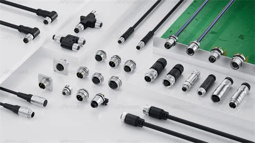
While not used in everyday consumer products, the DB50 connector remains a trusted choice in professional equipment. We offer a wide selection of DB50 connectors in different mounting and termination styles to meet various design requirements.
Understanding the Name: DB50 and DD50
Technically, the correct name is “DD-50.” However, the industry widely adopted the name “DB50.” Everyone understands this term, even if it’s not technically precise. D-sub connectors follow a naming pattern.
- D: Stands for “D-subminiature.” It refers to the D-shaped shield.
- D: The second letter represents the shell size, with the 50-pin version using a type “D” shell.
E = 9-pin shell
A = 15-pin shell
B = 25-pin shell
C = 37-pin shell
D = 50-pin shell
- 50: Simply means it has 50 pins.
Key Features of 50-Pin D-Sub Connectors
- High Pin Density: 50 pins within a compact housing make it ideal for dense signal configurations.
- Pin Layout: It has 50 pins arranged in three rows, maintaining a 2.77 mm pitch for reliable signal alignment.
- Robust Connection: The D-shaped metal shell prevents plugging it in backwards. It also provides good shielding from electrical noise (EMI/RFI). Two locking screws secure the connector in place, creating a stable and vibration-resistant connection.
- Versatile Mounting Options: Available in Cable mount, and PCB mount versions.
- Wide Compatibility: Standardized dimensions across the D-Sub family ensure cross-vendor interoperability.
Other Standard DB Connector Types
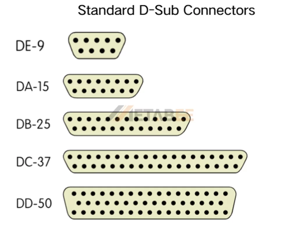
Other standard D-sub connectors include DB9, DB15, DB25, and DB37. They all have a pitch of 2.77 mm, but their shell sizes are different. The shell size determines the number of pins and the type of device it connects to.The table below shows the shell sizes and typical applications of standard D-sub connectors:
| Shell Size | Pin Number | Formal Name | Common Name | Typical Applications |
| E | 9 | DE-9 | DB9 | RS-232 Serial Ports |
| A | 15 | DA-15 | DB15 | VGA, Game Ports |
| B | 25 | DB-25 | DB25 | Parallel Printer Ports (LPT), SCSI |
| C | 37 | DC-37 | DB37 | Data Communications, Industrial Control |
| D | 50 | DD-50 | DB50 | Multi-channel I/O, PLC, instrumentation |
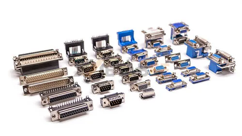
The diagram below shows standard D-sub connector types, including DE-9, DA-15, DB-25, DC-37, and DD-50, which differ in pin count and shell size to suit various applications.
Related Post: What is a D-Sub Connector? Everything You Need to Know About It
DB50 connector structure and design
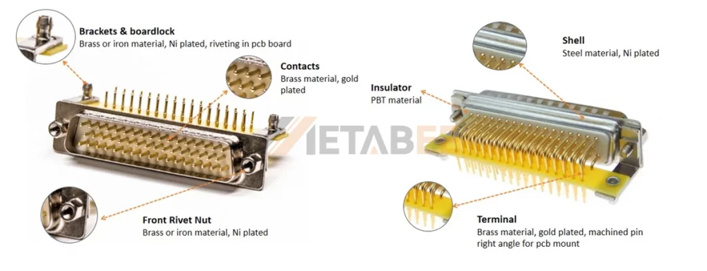
Physical Structure and Materials
The performance of a connector is determined by the materials of its core components. These materials ensure the connector’s corrosion resistance and long-term conductivity stability.
Shell:
- Material: Steel or zinc alloy, providing mechanical protection and electromagnetic shielding.
- Plating: Tin (standard) or Nickel (for wear and corrosion resistance).
Insulator:
- Material: PBT engineering plastic, compliant with the UL94V-0 flammability standard for safety.
Contacts:
- Material: Brass (standard) or Phosphor Bronze (for high mating cycles).
- Plating: Gold (low contact resistance, anti-oxidation, for critical signals) or Tin (cost-effective, for general applications).
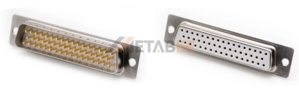
DB50 Pin Arrangement
The DB50 connector has 50 pins arranged in three rows. The layout is 17 pins on the top row, 16 in the middle, and 17 on the bottom (17-16-17). This arrangement allows a high number of signal lines in a compact connector while keeping the pitch at 2.77mm.
A typical DB50 pin arrangement diagram looks like this:
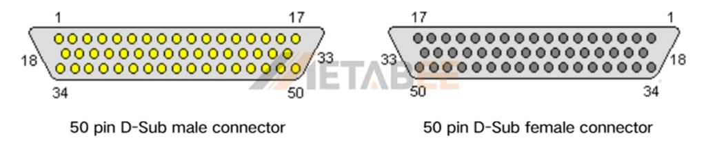
Key Point: The pin layout of a DB50 connector depends on its application. There is no universal standard. Different industrial or custom equipment may use different pin configurations.
Types of DB50 Connectors
Based on Gender
Gender refers to whether the connector has pins (male) or sockets (female). This is the most fundamental way to distinguish between two mating connectors.
- DB50 Male Connector: Has 50 pins and connects to the female side, often used on cables.
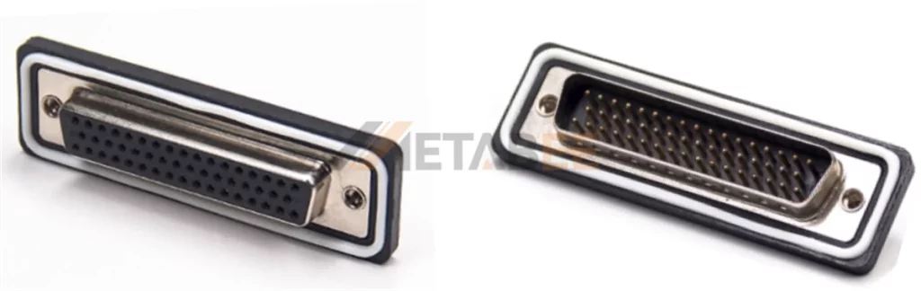
- DB50 Female Connector: Has 50 sockets that receive the male pins, usually mounted on devices.
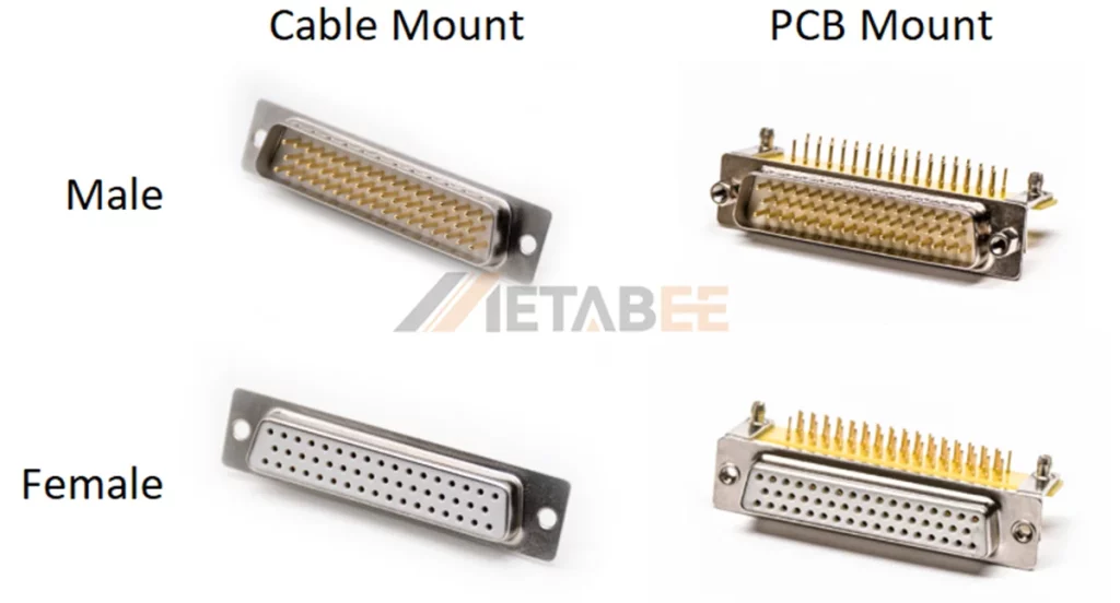
Based on Mounting Styles
DB50 connectors also come in two mounting methods. The most popular ones are cable mount, and PCB mount.
Cable Mount:
It is attached to the end of the cable and enclosed in a protective shell to make a data cable, and is not fixed to the device.
PCB Mount:
The connector is directly soldered or mounted onto the printed circuit board (PCB). Based on their pin and mounting orientation, they are subdivided as follows:
- Straight Mount: The connector’s pins pass vertically through the through-holes on the PCB and are then soldered on the opposite side. After installation, the connector body is perpendicular (90 degrees) to the PCB surface.
- Right-Angle Mount: The connector’s pins are pre-bent at a 90-degree angle, allowing it to be mounted on the edge of the PCB. After installation, the connector’s body is parallel to the PCB surface.
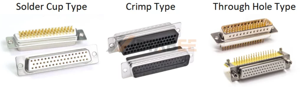
Based on Termination Methods
The DB50 connector supports three termination methods, which are typically categorized based on whether the connector is mounted on a cable or a PCB. For cable-mounted connectors, the common methods are solder cup and crimp. For PCB-mounted connectors, the method is through-hole termination.
- Solder Cup Type: Each contact has a small cup at the rear. Wires are manually soldered into the cups, offering strong and reliable joints. This type is ideal for prototypes and small production runs where flexibility matters.
- Crimp Type: Crimp contacts are attached to wires using a crimping tool. They provide consistent quality and are suitable for large-volume production. Crimp terminations allow quick replacement of individual pins without soldering.
- Through Hole Type: This version mounts directly onto printed circuit boards. The contacts extend through PCB holes and are soldered on the opposite side. It ensures stable signal paths in board-level connections.
3 Termination Methods for DB50 Connectors
When designing your system, always match the termination and mounting types to your wiring environment. Metabee offer all these configurations to meet different industrial and automation needs.
Electrical and Mechanical Specifications
DB50 connectors are built for stable performance in signal and power transmission. Their design ensures low resistance, high insulation, and reliable mating even in harsh environments.
Electrical Performance
The following table summarizes the typical electrical characteristics of standard DB50 connectors.
| Parameter | Typical Value | Description |
| Contact Current Rating | 5A per contact | Handles low to medium power signals |
| Rated Voltage | 500V RMS | Suitable for control and data lines |
| Contact Resistance | ≤ 20 mΩ | Ensures minimal signal loss |
| Insulation Resistance | ≥ 1000 MΩ @ 500V DC | Prevents leakage current |
| Dielectric Withstanding Voltage | 1000V AC / 1 minute | Guarantees electrical safety |
| Signal Transmission | Digital / Analog | Supports multi-signal transmission |
| Operating Temperature | –55°C to +105°C | Suitable for industrial use |
These parameters make DB50 connectors ideal for high-density applications that require consistent signal integrity and EMI protection.
Mechanical Properties
DB50 connectors are designed for durability and secure mechanical coupling. The following table lists the key mechanical specifications.
| Property | Typical Value | Notes |
| Insertion/Withdrawal Cycles | 200–500 times | Depends on contact plating |
| Insertion/Withdrawal Force | 30–70N | Describe the mechanical force required for insertion and removal |
| Locking Method | Screw lock | Ensures firm connection |
| Vibration Resistance | 10–500 Hz, 10 g | Stable under industrial vibration |
Shielding and Environmental Protection
The DB50 connector has a metal shell that blocks EMI (Electromagnetic Interference) and RFI (Radio Frequency Interference). Using it with grounding wires and a metal hood improves shielding and keeps signals stable.
However, EMI shielding is not always enough. Many harsh applications, such as industrial automation and outdoor equipment, also require environmental protection. Metabee offers a Waterproof DB50 Connector for these needs. This connector uses seals and a protective gland to block water and dust. This design allows for reliable operation in wet or outdoor environments, providing effective protection for sensitive devices.
Applications of DB50 Connectors
Across several professional fields, the DB50 connector provides a high-density, reliable connection for complex systems. The following table outlines its primary applications and the key reasons for its use in each area.
| Application Area | Specific Use Cases | Key Reason for Using DB50 |
| Legacy Computing | Multi-I/O cards. | High pin count for parallel data transfer. |
| Industrial & Control | Data Acquisition (DAQ), PLCs, robotics, motion control. | High I/O density, ruggedness, and secure locking. |
| Telecommunications | Patch panels, PBX phone systems, legacy network hardware. | Consolidation of many individual signal lines. |
| Test & Prototyping | Breakout boards, automated test equipment (ATE), lab use. | Easy access to a large number of test points. |
| Professional Audio | Multi-channel analog audio snakes, studio patch bays. | High channel count in a single, compact cable. |
Selecting the Right DB50 Connector
Key Selection Factors
When choosing a DB50 connector, consider the following aspects:
- Gender: male (pin) or female (socket) type.
- Shell material: metal for EMI protection, plastic for lightweight designs.
- Termination method: solder cup, crimp, or PCB Solder Tail.
- Mounting type: panel, cable, or pcb.
- Contact plating: gold-plated for low signal loss; tin-plated for cost efficiency.
Always match the connector with its counterpart to ensure proper mating and avoid pin alignment issues.
Conclusion
The DB50 connector continues to play an important role in signal transmission and control systems. Its standardized structure, solid mechanical design, and reliable electrical performance make it a trusted solution for industrial and laboratory use.
Compared with smaller D-Sub models, the DB50 offers higher pin density while maintaining mechanical strength. Its wide availability and long product life ensure compatibility in both existing and new designs.
Metabee offers a wide range of precision-designed DB50 connectors to meet industrial and automation needs, ensuring you can find the optimized model for your application.
Related Products
- DB50 connectors;
- DB37 Connectors;
- DB25 Connectors;
- DB15 Connectors;
- DB9 Connectors;
- Waterproof D-Sub Connectors;
- Combo D-Sub Connectors;
FAQs
Q1: How do I mount and connect a DB50 connector?
A: To install a DB50 connector, begin by confirming the correct mounting style for your application—such as panel, cable, or PCB mount. Then follow the manufacturer’s installation instructions carefully, using the appropriate hardware or tools to fasten and connect the connector securely to your device.
Q2: How do I identify the pin configuration for a DB50 connector?
A: You can determine the pin configuration of a DB50 connector by checking the product datasheet or technical documentation for your device. Each pin is numbered and assigned a specific signal or function, so always refer to the correct reference material before making any wiring connections.
Q3: What are the applications of a DB50 connector?
A: A DB50 connector is commonly used in industrial control systems, testing equipment, and data communication devices where compact, high-density, and reliable signal connections are required.
Q4: What cable should I use with a DB50 connector?
A: For general data transmission, 28–26 AWG shielded twisted-pair cables are recommended. These cables help reduce noise, minimize signal loss, and ensure stable and reliable performance in multi-signal applications.