If you are planning a marine electronics upgrade or troubleshooting a flaky onboard network, you’ve likely encountered the NMEA 2000 standard. This powerful protocol is the backbone of modern vessel management, enabling seamless data flow between devices. However, many installations fail due to simple errors in component selection and placement. This comprehensive guide breaks down the five core, non-negotiable hardware components required to build a reliable NMEA 2000 backbone. Lastly, we provide essential installation tips to ensure your system works flawlessly from day one.
Introduction: Defining NMEA 2000 and the Backbone Concept
Before diving into the hardware specifics, it is essential to establish a clear understanding of the NMEA 2000 protocol itself. This introductory chapter will first formally define NMEA 2000, explaining its technological roots and purpose. Next, we will focus on the central subject of this guide: the NMEA 2000 Backbone. This backbone serves as the critical physical foundation of any reliable marine network.
What is NMEA 2000?
NMEA 2000 (N2K) is a standardized, high-speed communication protocol based on CAN (Controller Area Network) technology, designed specifically for the marine electronics industry. This standard replaced the point-to-point analog wiring of NMEA 0183, marking a revolution in how marine devices communicate. This shift is comparable to replacing dial-up internet with fiber optic—it’s faster, more reliable, and infinitely more expandable.
NMEA 2000 utilizes Controller Area Network (CAN bus) technology, the same proven backbone system found in modern automobiles and industrial machinery. This standard allows marine electronic devices, regardless of their manufacturer, to communicate and share complex data. The data includes information such as GPS position, depth, engine diagnostics, and radar targets. This communication occurs over a single, standardized cable system at 250 kilobits per second.
What is the NMEA 2000 Backbone? The Foundation of Your Network
At the heart of every NMEA 2000 installation is the Backbone (sometimes called the Bus or Trunk).
The backbone is far more than just a cable; it is the central, powered communication highway that ties all electronic components together. Without a correctly designed and terminated backbone, data transmission fails, devices drop offline, and the entire system becomes unreliable. It is the single point of truth for both digital data and 12V DC power distribution to all connected, low-current devices.
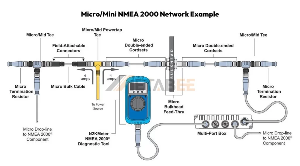
The structural rules of the NMEA 2000 standard demand a linear, non-branching bus topology. This means every device must connect to the main cable via a specific T-connector. Achieving reliability requires strict adherence to the standards and the correct use of five non-negotiable components. If even one of these components is missing or incorrectly placed, the network will fail.
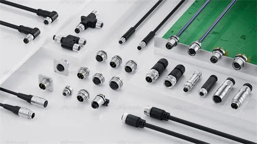
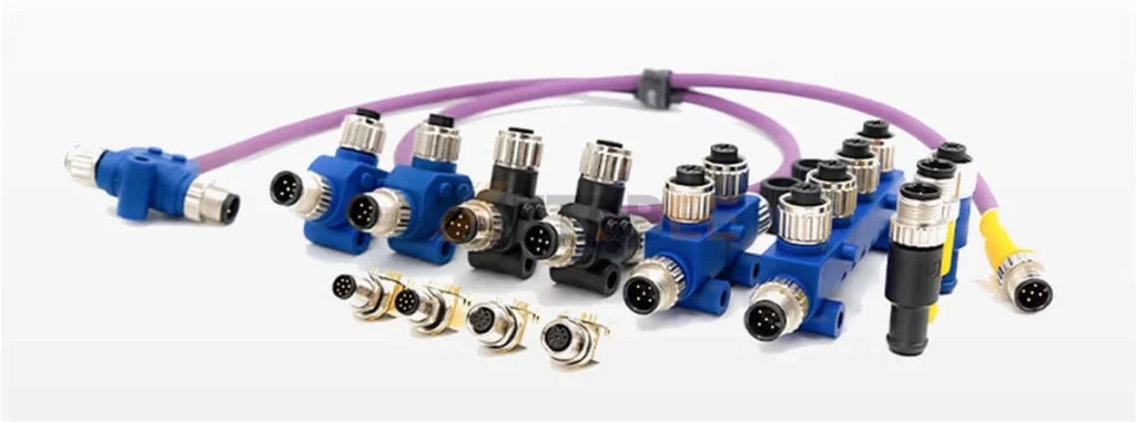
Connector Standards: M12 (Micro) and 7/8″ (Mini)
NMEA 2000 uses two primary connector standards derived from the industrial automation sector, corresponding to the cable types used for the backbone:
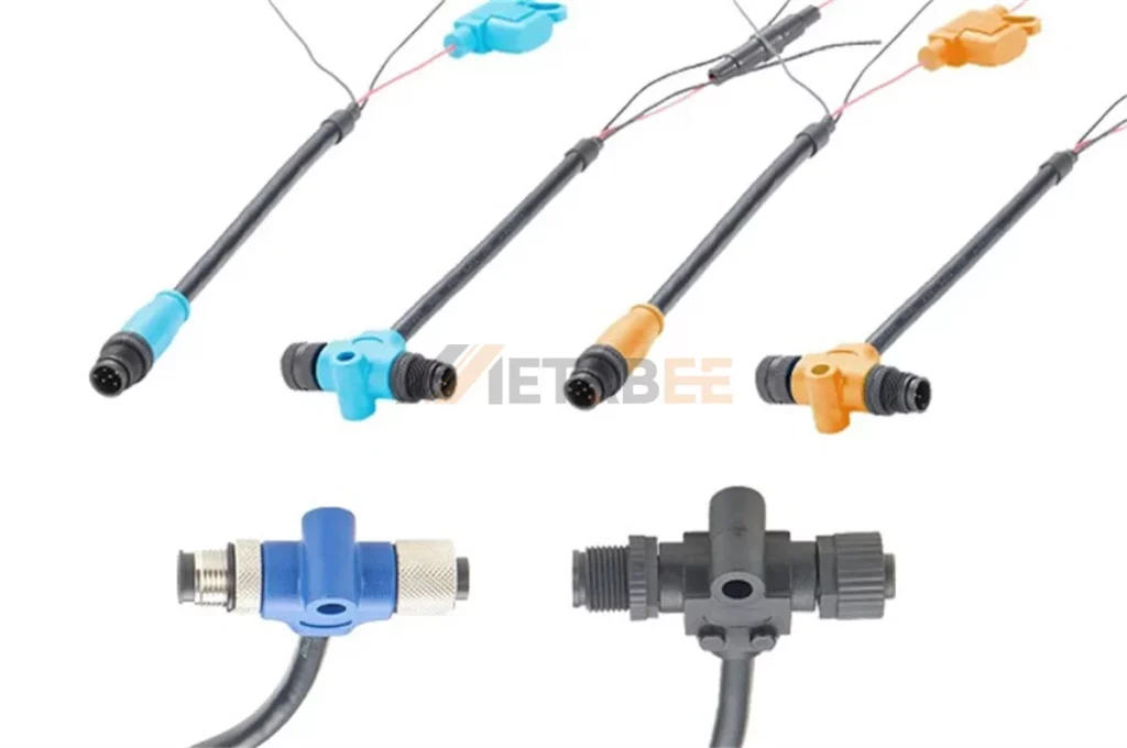
- M12 A-Coded 5-Pin Connectors (Micro Connectors): These are the smaller, typically black or gray, 5-pin connectors used for the standard Micro backbone cable. They are the most common interface for recreational vessels and are used for T-connectors, drop cables, and most devices.
- 7/8″ 5-Pin Connectors (Mini Connectors): These are the larger, heavy-duty connectors, used with the thicker gauge Mini backbone cable. They are necessary for extremely long cable runs or networks with high power demands (high total LEN count), typically found on large yachts or commercial vessels.
It is critical to note that M12 and 7/8″ connectors are not interchangeable; adapters must be used if you need to connect a Mini backbone segment to a Micro device or vice versa, although mixing is generally discouraged.

Related Post:
What is an M12 Connector? A Complete Overview
The Ultimate Guide to M12 Connector Pinout, Color Code, and Wiring Diagram
The 5 Essential NMEA 2000 Backbone Components
Building a reliable network starts with understanding the specific role and rules governing each of the 5 essential components. These parts work in concert to maintain signal integrity, manage power, and ensure every device can access the network.
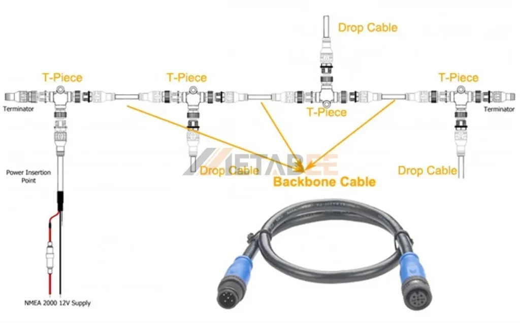
1. The Backbone Cable (The Data & Power Highway)
The backbone cable is the literal spine of the network, carrying both data (CAN High/Low) and power (12V DC supply and ground). Its quality and length are critical to network health.
| Specification | Detail | Importance |
|---|---|---|
| Micro Cable | Thinner, 5-pin connectors. Standard for most recreational vessels. | Maximum backbone length is 100 meters (328 ft). Handles up to 3 Amps of network current. |
| Mini Cable | Thicker gauge, larger connectors. Used for commercial or large vessel installations. | Can support much longer backbones (up to 200 meters) and higher current loads. |
| Construction | Must be shielded twisted-pair to resist electromagnetic interference (EMI). | Non-compliant or poorly shielded cables are a primary source of data corruption and intermittent faults. |
Key Takeaway: The type of backbone cable dictates the physical and electrical limits of your entire network. Always use NMEA 2000-certified cable with the correct male/female connectors.
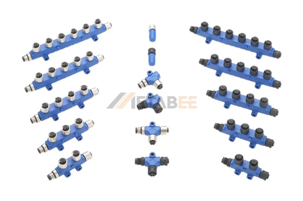
2. T-Connectors (The Connection Hubs)
T-connectors are the mandatory entry points for all devices and power sources onto the backbone. They are the fixed nodes in the system.
- Role: The T-connector acts as a junction point, maintaining the integrity of the main backbone line while allowing a “drop” connection to a device.
- Linear Topology: T-connectors must be connected directly to one another via short backbone cables. You must never connect a device directly to the end of the backbone cable.
- Counting Rule: When designing your network, you must account for one T-connector for every electronic device you plan to install, plus one dedicated T-connector for the power cable.
- Multi-Port Connectors: While specialized connectors (sometimes called network blocks or hubs) exist to cluster multiple drops in one area, they still function as a single T-connector connection point on the main backbone.
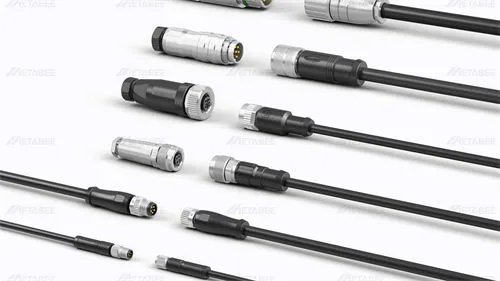
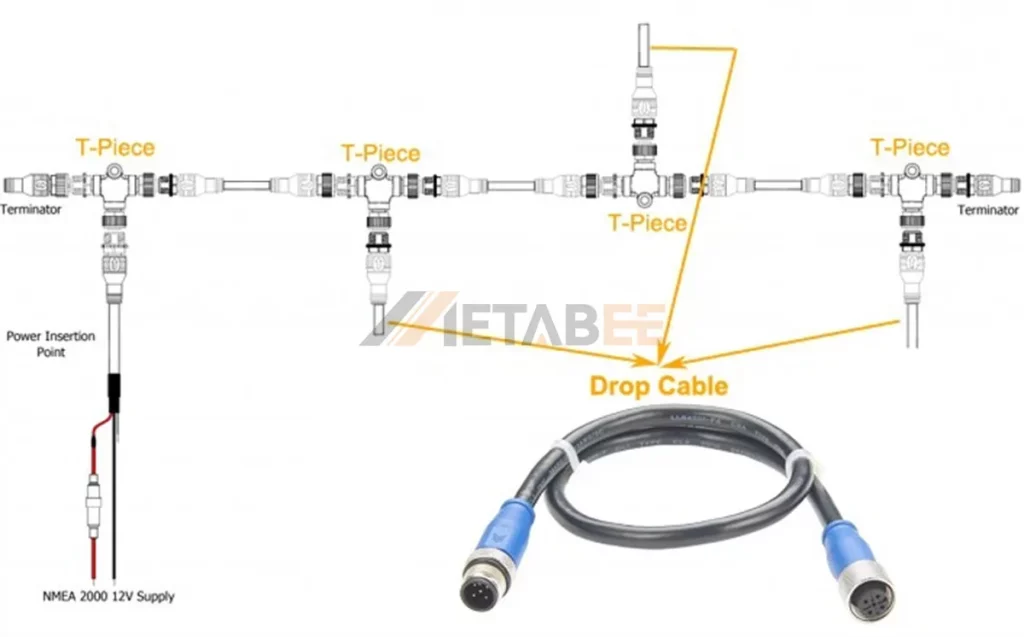
3. Drop Cables (The Device Leads)
Drop cables are the flexible leads used to connect an electronic device (like a chartplotter, transducer, or engine interface) to its designated T-connector on the backbone.
- The 6-Meter Rule: This is the most crucial compliance factor for drop cables. The maximum allowable length for any single drop cable is 6 meters (20 feet). This rule exists to prevent signal attenuation and reflections from degrading the network performance. If a device is farther than 6 meters from the backbone, the backbone itself must be extended closer.
- Power Function: Drop cables allow low-power devices (those drawing less than 1 Amp, or 20 LEN) to draw their power directly from the backbone, eliminating the need for separate power wiring to the battery.
- Non-Load-Bearing: Drop cables are never used to extend the main backbone run.
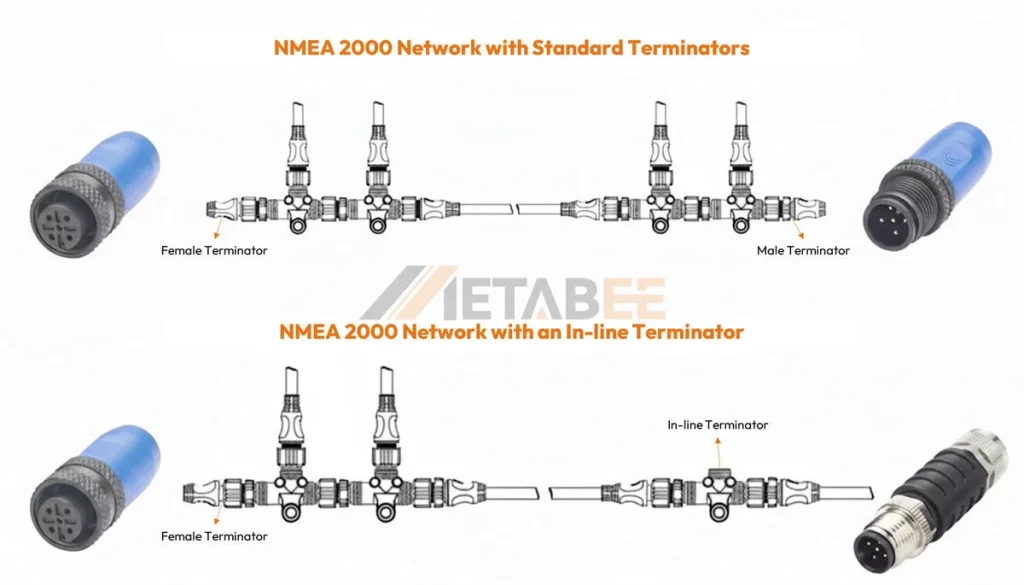
4. Terminators (The Signal Dampeners)
Termination is the most misunderstood, yet most critical, aspect of NMEA 2000. Terminators are simple resistors that perform an essential task: preventing data signal reflection.
- The Physics: When a data signal reaches the end of an open cable, it reflects back, causing signal interference or ‘echoes’ that the network interprets as data corruption.
- The 120-Ohm Solution: NMEA 2000 requires 120-Ohm resistors to be placed at each end of the backbone to absorb the signal energy, effectively damping out the reflections.
- The Placement Rule: A network must have exactly two terminators—one male and one female—placed only at the absolute physical ends of the backbone line. Any other configuration (one terminator, three terminators, or placement in the middle) will result in communication failure.
| Termination State | Resulting Impedance | Network Status |
|---|---|---|
| Correct (Two 120Ω resistors) | ~60 Ohms | Operational |
| Under-terminated (One resistor) | ~120 Ohms | Intermittent Failures |
| No Termination (Zero resistors) | Infinite Ohms | Complete Failure |
| Over-terminated (Three+ resistors) | <60 Ohms | Complete Failure |
5.The Power Cable (The Dedicated Energy Source)
While the backbone carries power, the NMEA 2000 power cable is the point where 12V DC voltage is introduced to the network.
- The Fused Requirement: The power cable must always contain an inline fuse, typically rated at 3 Amps. This protects the relatively small wires of the backbone from overcurrent damage.
- Source Isolation: The power cable should be connected to a dedicated, switched 12V DC power source, not the ignition or starter battery. This ensures the network is stable and can be powered independently of the engine.
- Load Equivalency Number (LEN): Every NMEA 2000 device is assigned a LEN, where 1 LEN = 50mA (0.05 Amps). The total cumulative LEN of all devices on the network dictates the network’s total power consumption. This total load must not exceed 60 LEN (3 Amps) to stay within the safe operating limits of a standard Micro backbone.
NMEA 2000 Backbone Installation Guidance (Putting the Components Together)
Having the right components is only half the battle; knowing how to assemble them according to the NMEA standard ensures long-term reliability.
A. Design Phase: Mapping the Network
Before buying a single component, you must plan the network’s topology, which is the physical layout of the cables and connections.
- Device Inventory: List every device you intend to connect. Assign each a T-connector on your diagram.
- Determine Backbone Path: Identify a clear, linear route (e.g., stern to helm) that runs physically closest to the clusters of devices. The goal is to keep the backbone long and the drop cables short.
- Calculate Cable Lengths: Measure the distance for the main backbone run. Verify the distance from each T-connector location to its connected device, ensuring every drop cable is less than 6 meters.
B. The Power Insertion Point: Center is Best
The location where you connect the power cable is crucial for minimizing voltage drop, which can cause devices at the ends of the backbone to brown out.
- Optimal Placement: The power T-connector should be placed as close as possible to the electrical midpoint of the network. This means the total current draw should be roughly equal on the cable segments running in either direction from the power T.
- Physical Midpoint Rule of Thumb: For simpler networks, placing the power T near the physical center of the backbone is a good, safe practice.
- Powering Large Networks: For networks with very high LEN counts or long runs, you may need to introduce two separate power insertion points (both from the same battery source) to maintain a stable 12V at all points.
C. Assembly and Termination
The physical assembly requires careful, methodical work to ensure solid, weather-tight connections.
- Cable Management: Run and secure the backbone cable, avoiding sharp bends and isolating it from sources of high-voltage interference (like VHF antenna lines or engine ignition wires).
- Assembly Sequence: Connect the T-connectors sequentially along the main run using short backbone cables.
- Connecting Devices: Attach the drop cables from the devices to the open port on each T-connector.
- Final Termination: Confirm the two terminators are screwed securely onto the last male and female ports at the very ends of the backbone. Do not install a terminator until the entire run is physically complete.
D. The Ohm Test: The Ultimate Verification Check
After installation, the only way to scientifically verify your backbone is properly terminated is by conducting a simple resistance test using a standard multimeter. This step is non-negotiable for a professional installation.
- Power Off: Disconnect the NMEA 2000 power cable from its battery source.
- Disconnect: Remove one terminator from one end of the backbone.
- Test: Connect the multimeter leads to the two data pins (CAN High and CAN Low) on the open T-connector port.
- Result: A correctly terminated network (with only the single remaining 120-Ohm resistor installed at the opposite end) should read approximately 60 Ohms (54 to 66 Ohms is acceptable).
- Diagnosis: If the reading is close to 120 Ohms, you only have one terminator installed. If the reading is less than 50 Ohms, you likely have a short, or too many terminators are present.
| Multimeter Reading | Diagnosis | Corrective Action |
|---|---|---|
| ~60 Ohms | Correctly terminated. | Power on the network. |
| ~120 Ohms | Only one terminator is present. | Check the opposite end of the backbone for the missing terminator. |
| 0 Ohms | Short circuit on the data lines. | Check cable runs and T-connector pins for damage. |
| Open Line (OL/Infinity) | Cable break or missing components. | Check all cable connections and look for a physical break in the line. |
Conclusion: Build Reliability from the Core
The NMEA 2000 backbone is a robust and powerful standard, but its strength is entirely dependent on its proper construction. You ensure maximum data integrity and power reliability by strictly adhering to the standards. This adherence involves properly utilizing the five essential components of the network. These components are the Backbone Cable, T-Connectors, Drop Cables, Terminators, and Fused Power Cable.
Skipping the Ohm test or failing to respect the 6-meter drop cable rule are the two most common errors that lead to costly, frustrating intermittent system failures.
For businesses and installers, reliability is everything. Mastering these components and their correct placement is the difference between a satisfied, long-term customer and a complicated, time-consuming service call.
Need to build your system today? Explore our selection of NMEA 2000 components designed for optimal marine network performance.
Related Products:
- NMEA 2000 Connectors
- NMEA 2000 Backbone, Drop, and Power Cables
- NMEA 2000 Tee Connectors
- NMEA 2000 Terminators
FAQs
Q: What are the five essential components required for a functional NMEA 2000 backbone?
A: The five non-negotiable components are the Backbone Cables, T-Connectors, Drop Cables, Terminators, and the Power Cables.
Q: What is the maximum length allowed for a single NMEA 2000 Drop Cable?
A: The maximum allowed length for any single drop cable connecting a device to a T-connector is strictly 6 meters (20 feet).
Q: Why do I need terminators, and how many should I use?
A: Terminators (120-Ohm resistors) are necessary to absorb data signals at the ends of the network, preventing signal reflection (echoes) that cause data corruption. You must use exactly two terminators.
Q: Where exactly should the two terminators be placed?
A: They must be placed at the absolute physical ends of the linear backbone cable run, and nowhere else.
Q: When testing the network, what Ohm reading indicates correct termination?
A: The backbone should measure approximately 60 Ohms between the CAN High and CAN Low data pins.
Q: Where is the best place to connect the Fused Power Cable to the backbone?
A: The power T-connector should be located as close as possible to the electrical midpoint of the network to ensure even voltage distribution and minimize voltage drop across the entire system.
Q: What is the main difference between Micro (M12) and Mini (7/8″) connectors?
A: Micro (M12) is the standard size for recreational vessels, while Mini (7/8″) is heavy-duty and used for much longer backbone runs or high-power-demand networks.
Q: What is the purpose of the Load Equivalency Number (LEN)?
A: LEN is a measure of a device’s current draw (1 LEN = 50mA). The total cumulative LEN of all devices dictates the network’s total power consumption and ensures the standard 3-Amp limit is not exceeded.