In the modern era of booming intelligent driving and high-speed in-vehicle entertainment systems, stable and reliable high-speed data transmission has become crucial. To meet this demand, HSD connectors are key components designed for this purpose. Accordingly, this article will take you on an in-depth exploration of the world of HSD high-speed data connectors. It provides a comprehensive analysis of their design structure, pin definitions, coding systems, main performance, and key applications, and offers a practical selection guide.
What is an HSD (High-Speed Data) Connector?
Definition
An HSD connector is a shielded, high-speed differential connector system designed for automotive data transmission. Moreover, it supports frequencies up to 6 GHz and enables high-bandwidth digital interfaces such as LVDS, USB, Ethernet, and MOST. As a result, HSD connectors deliver exceptional signal integrity, low crosstalk, and robust EMC performance required by modern vehicle networks.
Key Features
- High Data Rates: Supports transmission speeds up to 6 Gbps (depending on the generation and cable quality).
- Interference Immunity: The shielded twisted quad design offers superior protection against crosstalk and external noise.
- Retention & Durability: Features primary and secondary locking mechanisms to prevent accidental disconnection due to vehicle vibration.
- Scoop Proof: The design prevents the pins from being bent or damaged during the mating process.
HSD Design Structures and Materials
Components and Materials
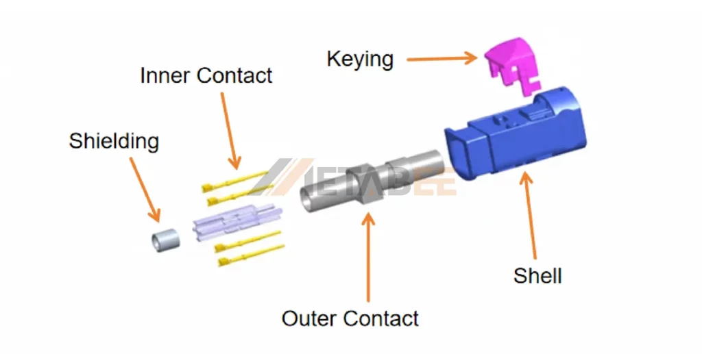
An HSD connector typically consists of signal contacts for differential pairs, a shield, and a connector housing with mechanical latching and coding features to prevent incorrect mating.
The HSD connector distinguishes itself with a Star Quad concept.
- Keying(Coding): HSD connectors use a mechanical and color-coded system to prevent mismating, ensuring that a plug can only be connected to its correct counterpart.
- Shell: Robust plastic housing made from automotive-grade polymers (PA), designed to withstand vibration and temperature fluctuations.
- Inner Contact: The inner contacts consist of four high-precision signal terminals arranged in a Star Quad layout. Furthermore, these contacts are usually fabricated from Copper Alloy with selective gold plating to ensure low contact resistance, excellent conductivity, and long-term corrosion resistance.
- Outer Contact: The outer contact forms the first layer of shielding around the inner terminals. By doing so, it enhances the robustness of the signal path and supports proper grounding.
- Shielding: A 360-degree die-cast metal shield ensures high EMI (Electromagnetic Interference) and EMC (Electromagnetic Compatibility) immunity, which is critical in the noisy electrical environment of a vehicle.
Structure, materials, and plating of HSD connectors:
| Component | Material |
|---|---|
| Shell | PA |
| Inner Contact Material | Copper Alloy |
| Inner Contact Plating | Gold-Plated |
| Outer Contact Material | Zinc Alloy |
| Outer Contact Plating | Nickel Plated |
| Shielding | Shielded |
Shielded Twisted Quad (STQ) Structure
- The STQ concept is central to HSD pinout design.
- Structure: An STQ cable consists of two individually twisted pairs (two differential pairs) housed within a single, continuous shield and an outer jacket.
- This structure is designed to transmit high-speed differential signals while minimizing interference from external sources and crosstalk between signals.
Supported Protocols
HSD connectors are versatile and support various communication protocols, including:
- LVDS (Low-Voltage Differential Signaling): The primary application for video transmission.
- Automotive Ethernet (100Base-T1, 1000Base-T1): For networking within the vehicle.
- USB 1.0, 2.0, and 3.0: Connecting consumer devices to the car’s head unit.
- APIX (Automotive Pixel Link): For high-resolution displays.
- GVIF (Gigabit Video Interface) and FPD-Link.
HSD Pinout
Understanding the HSD pinout is essential for cable assembly and PCB layout design.
Standard Contact Layout
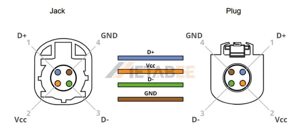
HSD connectors employ a shielded-twisted-quad (STQ) cable structure to ensure superior signal integrity and interference immunity. They use a 4-pin configuration. The pins are arranged in a square pattern to form two differential pairs (4 signal conductors). Some variants add additional contacts for power or ground, resulting in, e.g., a “4 + 2” or “4 + n” pin layout (4 signal pins + discrete pins).
HSD plug and jack in schematic view with pin assignment:
HSD Coding
This section describes the coding (Keying) system of the HSD connector.
Coding Explained and Purpose
HSD connectors utilize a mechanical coding system (keying) and color coding. Specifically, coding refers to a mechanical and visual keying system built into the connector housings. The primary purpose of HSD coding is to prevent mismating and ensure correct plug-to-jack pairing.
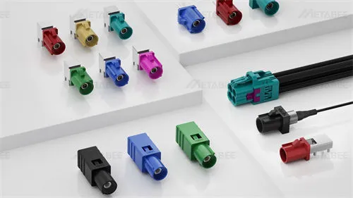
Color Coding
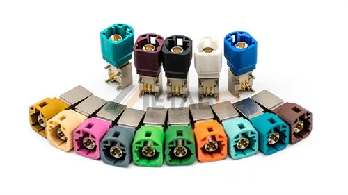
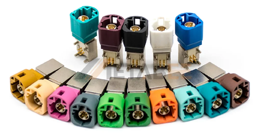
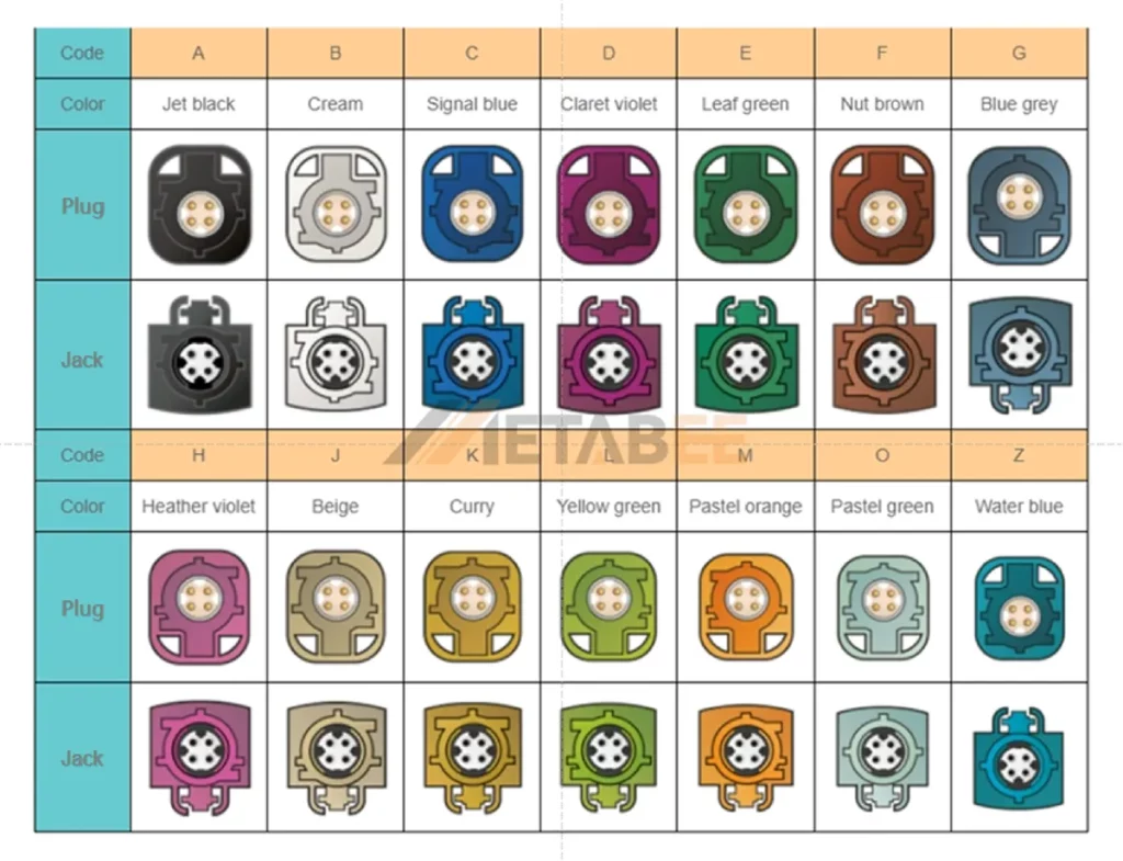
HSD connector systems employ a 14 color-coded scheme linked to the coding letters (A, B, C, etc.) so that each coded connector corresponds to a distinctive housing color.
14 Codes and Colors of HSD Plug and Jack:
HSD Connectors Types
High-Speed Data (HSD) connectors are engineered in various configurations to meet the diverse and specific demands of modern automotive systems. Primarily, they are categorized by the number of pins and the interface design. Therefore, understanding these variations is crucial for selecting the optimal connector for any given application, ensuring both signal integrity and mechanical reliability.
By Pins
The pin configuration is a fundamental characteristic of an HSD connector, directly influencing its application and data-handling capabilities. Specifically, the arrangement is typically based on the Shielded Twisted Quad (STQ) cable structure, which consists of two differential signal pairs.
In a standard LVDS setup, the pins are typically assigned as follows:
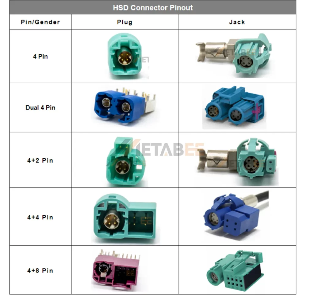
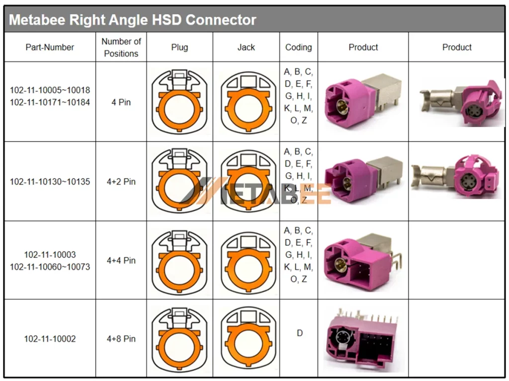
- 4 Pin HSD Connectors
- Dual 4 Pin HSD Connectors
- 4+2Pin HSD Connectors
- 4+4Pin HSD Connectors
- 4+8Pin HSD Connectors
By Interface Types
Beyond pin counts, HSD connectors are distinguished by their physical interface design.
Common interface types include:
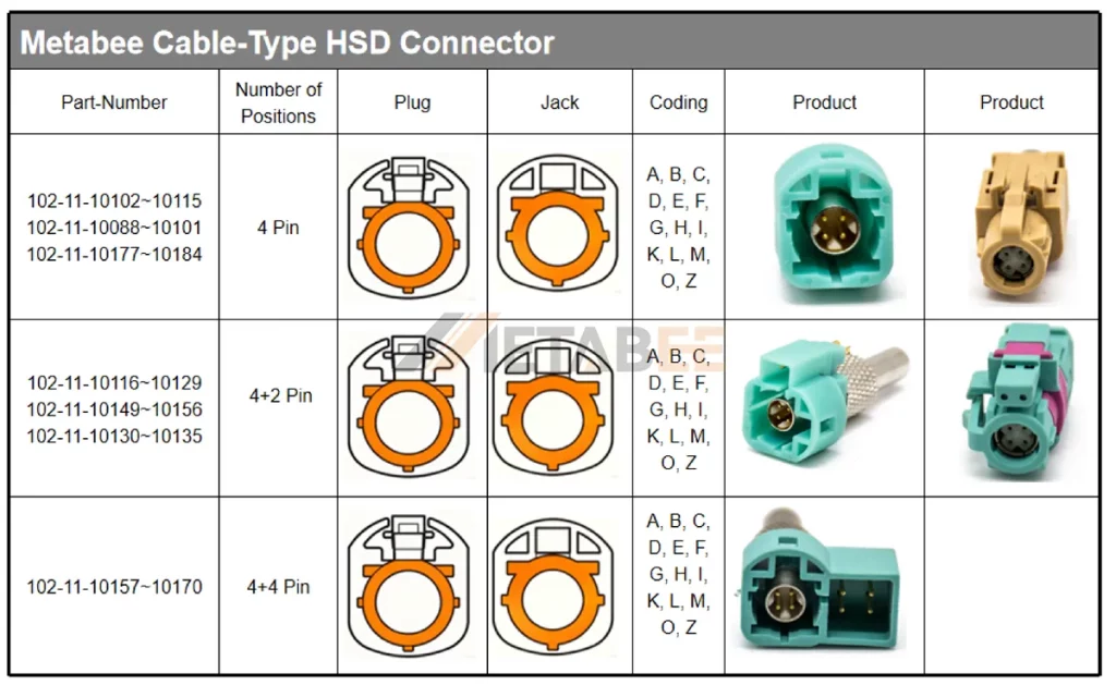
HSD Cable Type Connectors
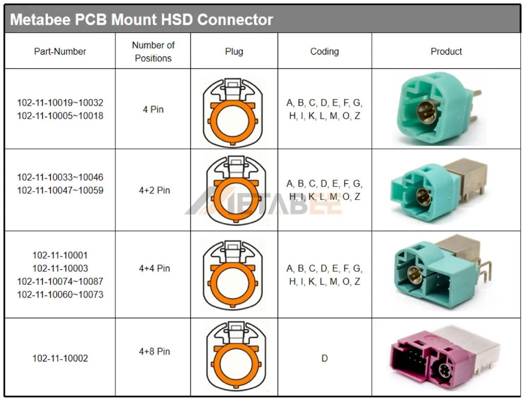
HSD PCB Mount Connectors
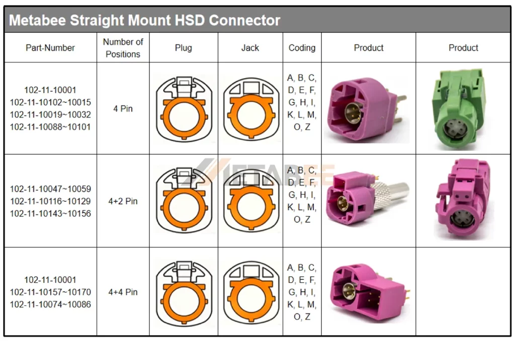
HSD Straight Connectors
HSD Right Angle Connector
Main Specifications
The performance of High-Speed Data (HSD) connectors is defined by stringent specifications across electrical, mechanical, and environmental criteria. Therefore, these specifications ensure reliable operation, signal integrity, and durability within the harsh automotive environment.
| Locking Mechanism | Push-on |
| Impedance | 100 Ohms |
| Frequency Max | 2 GHz |
| Insulation Resistance | ≥ 1000 MΩ |
| Withstanding Voltage | 250 V rms |
| Operating Voltage | 100 V rms |
| Durability | ≧25 Cycles |
| IP Rating | IP67 |
| Signal Contact Resistance | 10 mΩ Max |
| Outer Contact Resistance | 7.5 mΩ Max |
| Mating cycles | ≥25 Cycles |
| Temperature Range | -40°C to +105°C |
Key Applications
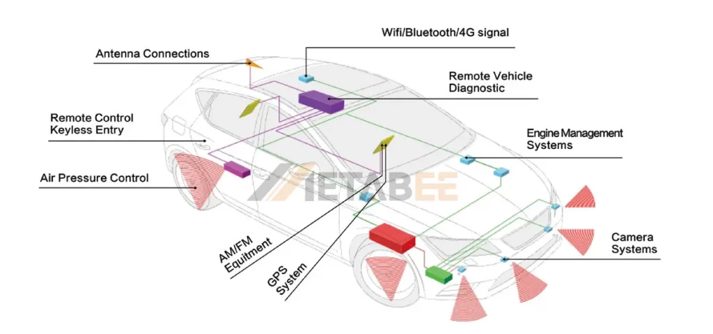
HSD connectors are widely used in automotive digital systems, including, but not limited to:
- Infotainment Systems: Connecting Head Units to High-Resolution Displays (cluster, center stack, rear-seat entertainment).
- ADAS (Advanced Driver Assistance Systems): Transmitting data from LIDAR, RADAR, and high-res cameras to the processing unit.
- USB Ports: Connecting the internal hub to the user-facing USB dashboard port.
- Telematics: Connecting antenna modules to the TCU (Telematics Control Unit).
How to Choose the Right HSD Connector?
When selecting an HSD connector for a given application, consider:
Data Speed Rate
Ensure the connector meets your bandwidth needs. Standard HSD is great for USB 2.0 and LVDS. On the other hand, for higher speeds (like USB 3.0 or 4K video), ensure the manufacturer certifies the connector for higher frequencies (sometimes referred to as HSD eXtended).
Coding Type
Identify the application function (e.g., USB, Display). Select the corresponding Coding (Color) to prevent assembly line errors.
Number of Positions
HSD connectors typically come in single-port or multi-port (multi-way) configurations
- Single-Port: Standard. Suitable for one-to-one connections, like a single camera link.
- Multi-Port: Two ports in one housing, saving PCB space. Ideal for applications that require integrating several high-speed channels into a single, compact module, such as a centralised infotainment head unit, saving space and simplifying harness routing.
Frequency Range & Bandwidth
Ensure the HSD connector and cable assembly can meet the frequency/bandwidth demands of the protocol (e.g., LVDS video, Ethernet, USB, SerDes links).
Space Constraints
Automotive environments are often tight on space. The physical size of the connector is a critical factor.
- Straight: Standard vertical PCB mount.
- Right Angle (R/A): For tight spaces behind the dashboard or head unit.
Environmental Requirements
HSD connectors in automotive applications must withstand harsh operating conditions.
- Temperature Range: The connector must operate reliably across the vehicle’s required temperature spectrum, typically from -40°C to +105°C or higher.
- Vibration and Shock: Ensure the connector meets established automotive standards (e.g., USCAR-2, LV 214) for vibration resistance and mechanical shock to prevent intermittent connectivity.
- IP Rating: For connectors used in exterior or under-hood applications, the IP6K7, IP6K9K ratings are essential to protect against moisture, dust, and pressure washing. Accordingly, the selection must include proper sealing elements.
The Leading High-Speed Data Connector Factory and Manufacturer
Notable manufacturers and suppliers offering automotive-grade HSD connectors include:
- TE Connectivity: They widely use the HSD portfolio supporting up to 6 Gbps and multiple protocols (LVDS, Ethernet, USB).
- Amphenol: They offer HSD connector systems compliant with USCAR-2, with strong mechanical retention and hybrid data/power capabilities. Their HSD solutions are widely used in American and European vehicles.
- Rosenberger: The pioneer of the HSD interface. They set the industry standard for high-frequency automotive connectors. They offer variants with power pins (HSD+2, +4, +8)
- Metabee: It is a growing manufacturer specializing in automotive connectivity. Moreover, they provide cost-effective and fast delivery HSD solutions for the aftermarket and OEM supply chains.
- Renhotec: Known for a wide range of RF and automotive connectors, providing flexible customization for HSD cable assemblies.
Conclusion
The HSD connector is a critical component in the architecture of modern vehicles. It can transmit high-speed data while shielded from the intense electromagnetic noise of a car. Therefore, it is indispensable for Infotainment and ADAS. Understanding pinout structures, coding, specifications, and selection criteria helps you choose the optimal connector for your application and ensures robust performance across the entire automotive network. Specifically, selecting the appropriate HSD variant requires matching data rate, coding, number of contacts, environmental tolerance, and mechanical form factor to the application’s demands.
Related Products
Frequently Asked Questions (FAQ)
Q1: What is the difference between HSD and FAKRA connectors?
A: FAKRA is a coaxial connector (1 pin) designed primarily for RF signals like Radio, GPS, and GSM. In contrast, HSD is a 4-pin differential connector designed for digital high-speed data (LVDS, USB, Ethernet).
Q2: What is the typical impedance of an HSD connector and cable assembly?
A: The standard characteristic impedance for the differential pairs within an HSD connector and its corresponding cable assembly is 100 Ohms. This is because the impedance is crucial for maintaining signal integrity and minimizing reflection losses for differential signaling protocols.
Q3: How many pins does a standard HSD connector have?
A: A standard HSD connector typically uses a 4-pin interface arranged as a differential pair (D+, D–, D+, D–). Additionally, multi-channel versions, including HSD 4+2 pin, HSD 4+4 pin, and HSD 4+8 pin, are available for systems requiring multiple high-speed data ports in a single connector housing.
Q4: Can HSD connectors transmit power?
A: Standard HSD connectors are for data. However, the HSD+2 and HSD+4 variants include dedicated power pins to supply power to remote devices, in addition to data transmission.
Q5: What are the applications of HSD connectors?
A: HSD connectors are used for high-speed differential data transmission in automotive systems, including infotainment, ADAS sensors, cameras, radar, and high-bandwidth communication modules.
Q6: What are the typical supported data rates and bandwidths for HSD connectors?
A: HSD connectors are typically capable of handling data rates up to 6 Gbps and higher, depending on the specific product generation.
Q7: What do the different HSD coding colors mean?
A: The purpose of color coding is to prevent mismating between incompatible interfaces. Each color represents a specific application or signal type.
For example:
- Green: Ethernet
- Purple: ADAS camera links
- Blue: USB 3.x
- Black: General data or LVDS
- Brown: K-line or diagnostics
- White: Audio/Sound Systems
Q8: Can HSD connectors be used interchangeably with FAKRA connectors?
A: No. HSD and FAKRA connectors serve different functions and are physically incompatible.
- HSD Connectors are suitable for digital data transmission (Ethernet, USB, LVDS).
- FAKRA Connectors are suitable for RF signals (GPS, GSM, Satellite Radio).