In the vast landscape of electromechanical components, few interfaces have achieved the ubiquity of the Universal Serial Bus (USB). However, for the systems engineer or procurement manager, the USB connector is far more than a ubiquitous consumer port; it is a precision-engineered interface that must balance increasingly conflicting demands: higher data rates (up to 40 Gbps), substantial power delivery (up to 240W), and miniaturization, all while maintaining mechanical robustness in harsh environments.
This article moves beyond the basic datasheets to explore the physical layer (PHY) of USB connectors. We will dissect the evolution of pinouts, analyze critical electromechanical parameters, and provide a technical framework for selecting the right interconnect solution for industrial, automotive, and high-reliability applications.
What is a USB Connector?
At its most fundamental level, a USB (Universal Serial Bus) connector is the standardized electromechanical interface that bridges a host controller (such as a computer or industrial PC) and a peripheral device. Legacy interfaces required dedicated ports for specific functions, such as parallel ports for printers or serial ports for modems. In contrast, the USB connector was architected to be a universal solution for both data communication and DC power transmission.
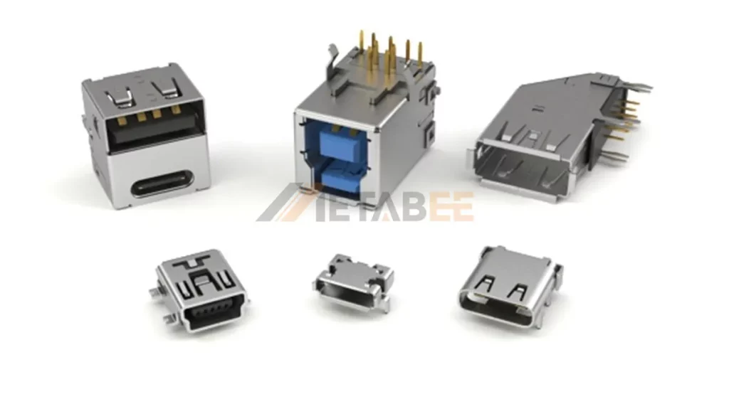
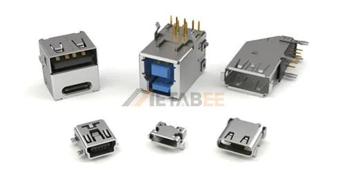
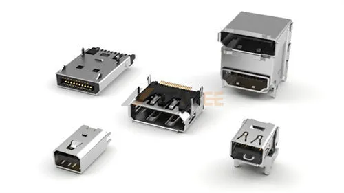
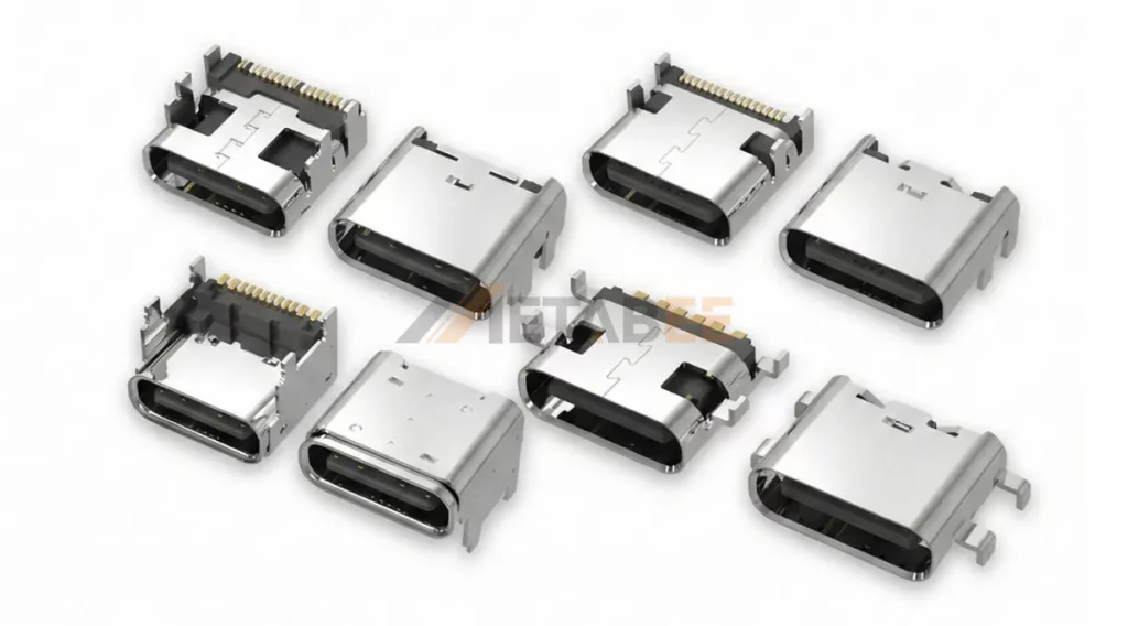
Metabee USB Connectors
This universality is underpinned by rigorous compliance standards—such as USB-IF (functional compliance), EIA-364 (electrical/mechanical testing), and USCAR-30 (automotive specifications)—that ensure interoperability across billions of devices globally.
For the design engineer, the USB connector is defined not just by its geometry, but by its functional requirements:
- Hot-Swappability: The mechanical design allows for safe insertion and removal while the system is powered, requiring precise contact sequencing (ground pins mate first, release last) to prevent electrostatic discharge (ESD) damage.
- Bidirectional Communication: It facilitates complex handshake protocols, allowing devices to negotiate power roles (Source/Sink) and data rates dynamically.
- Power Delivery: It serves as a power conduit, evolving from a simple 5V supply to a sophisticated high-voltage power delivery system capable of driving everything from sensors to laptops.
The Evolution of USB Architectures & Pinouts: From 4 Pins to 24
The transition from USB 2.0 to USB4 represents a fundamental shift in connector architecture, moving from simple low-speed serial buses to complex, high-frequency differential signaling systems. Understanding this evolution is critical for PCB layout and signal integrity planning.
1. USB 2.0: The Foundation (4 Pins)
The legacy USB 2.0 standard utilizes a simple 4-pin geometry (Type-A/B) consisting of:
- VBUS (+5V): Power supply.
- D- / D+: A single differential pair for half-duplex data transmission (up to 480 Mbps).
- GND: Ground return.
- (Shield): While not a pin, the metal shield is critical for EMI containment.
USB 2 Type-A and Type-B Pinout Diagram
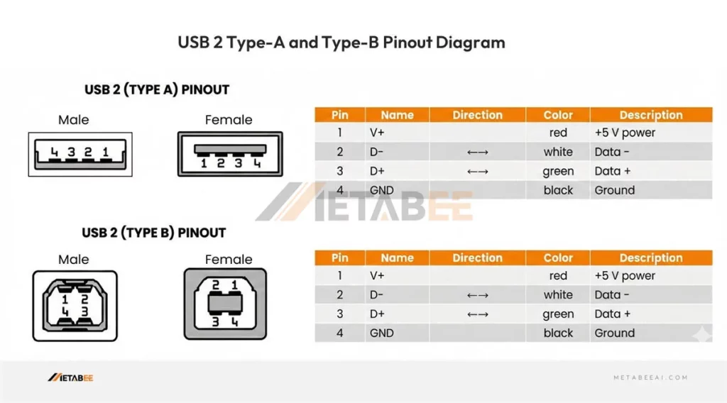
Engineering Note: In this architecture, signal integrity is relatively easy to manage. The primary concern is typically voltage drop across the VBUS contact in longer cable runs.
2. USB 3.0 / 3.2 Gen 1 & 2: The Introduction of SuperSpeed (9 Pins)
To achieve SuperSpeed (5 Gbps) and SuperSpeed+ (10 Gbps), the architecture expanded significantly. The standard USB 3.0 Type-A connector retains the original 4 pins for backward compatibility but introduces 5 additional contacts recessed deeper into the housing:
- StdA_SSRX- / StdA_SSRX+: A differential pair for receiving SuperSpeed data.
- StdA_SSTX- / StdA_SSTX+: A differential pair for transmitting SuperSpeed data.
- GND_DRAIN: A ground drain wire specifically for signal integrity management of the high-speed pairs.
USB 3 Type-A and Type-B Pinout Diagram
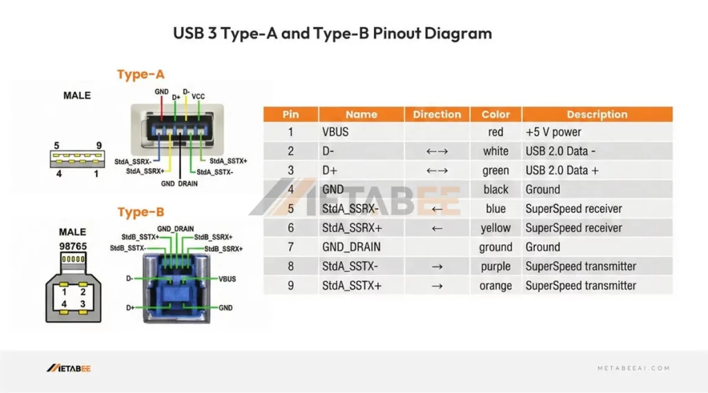
Engineering Note: This architecture introduced full-duplex communication. The physical separation of the TX and RX pairs is critical to minimize Near-End Crosstalk (NEXT), a challenge that becomes more pronounced as frequencies rise.
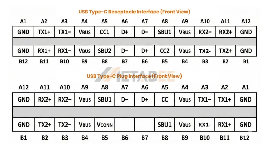
3. USB 3.2 Gen2x2 / USB4 & Type-C: High-Density Convergence (24 Pins)
The USB Type-C connector is a marvel of micro-mechanics. It packs 24 pins into a form factor roughly the size of the legacy Micro-B, yet it handles USB4 (40 Gbps) and Power Delivery (PD).
- Symmetry: Two sets of 12 pins allow for reversible mating.
- CC1 / CC2 (Configuration Channel): These pins are the “brains” of the operation, negotiating power roles (Source/Sink) and Alternate Modes (DP, HDMI, PCIe).
- SBU1 / SBU2 (Sideband Use): Low-speed lines used for auxiliary functions in Alternate Modes.
- VBUS: Four VBUS pins are distributed to handle higher currents (up to 5A) efficiently.
USB Type-C Connector Pinout Diagram
| Pin | Signal Name | Description | Mating Sequence | Pin | Signal Name | Description | Mating Sequence |
|---|---|---|---|---|---|---|---|
| A1 | GND | Ground return | First | B12 | GND | Ground return | First |
| A2 | TX1+ | Positive half of first TX differential pair | Second | B11 | RX1+ | Positive half of first RX differential pair | Second |
| A3 | TX1- | Negative half of first TX differential pair | Second | B10 | RX1- | Negative half of first RX differential pair | Second |
| A4 | VBus | Bus Power | First | B9 | VBus | Bus Power | First |
| A5 | CC1 | Configuration Channel | Second | B8 | SBU2 | Sideband Use(SBU) | Second |
| A6 | D+ | Positive half of the USB 2.0 differential pair- Position 1 | Second | B7 | D- | Negative half of the USB 2.0 differential pair-Position 2 | Second |
| A7 | D- | Negative half of the USB 2.0 differential pair- Position 1 | Second | B6 | D+ | Positive half of the USB 2.0 differential pair-Position 2 | Second |
| A8 | SBU1 | Sideband Use(SBU) | Second | B5 | CC2 | Configuration Channel | Second |
| A9 | VBus | Bus Power | First | B4 | VBus | Bus Power | First |
| A10 | RX2- | Negative half of second RX differential pair | Second | B3 | TX2- | Negative half of second TX differential pair | Second |
| A11 | RX2+ | Positive half of second RX differential pair | Second | B2 | TX2+ | Positive half of second TX differential pair | Second |
| A12 | GND | Ground return | First | B1 | GND | Ground return | First |
Engineering Note: At 40 Gbps (20 GHz Nyquist frequency), the Type-C connector acts as a transmission line. Impedance discontinuities must be minimized. The connector footprint on the PCB requires precise fan-out strategies to avoid signal reflection.
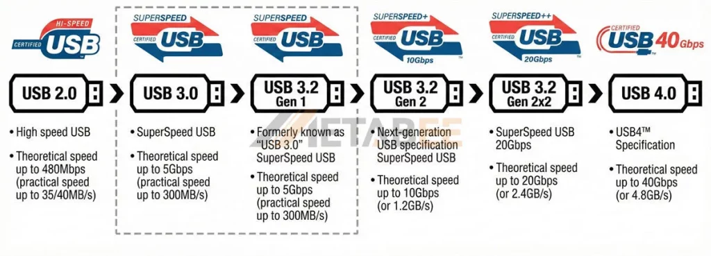
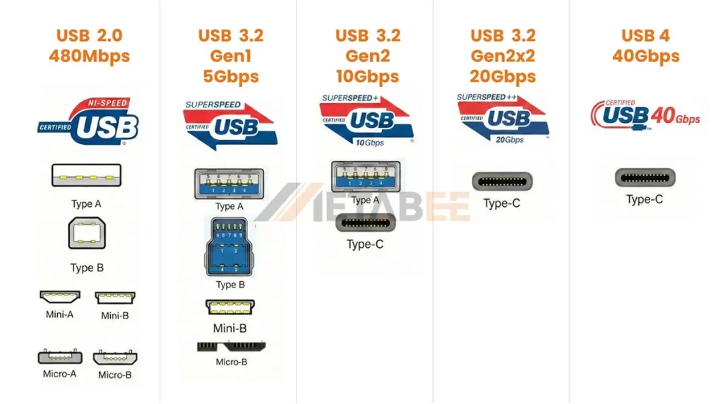
USB Specification Comparison: 2.0 to 4.0
Below is a detailed comparison table of USB standards ranging from USB 2.0 to USB 4.0. This overview covers the theoretical bandwidth, estimated real-world speeds, the often-confusing naming conventions, and the compatible physical connector types for each generation.
| Specification Version | Marketing Name (Logo) | Max Theoretical Bandwidth | Est. Practical Speed (Ref. Image) | Aliases / Old Names (Confusion Points) | Common Physical Interface Types |
| USB 2.0 | Hi-Speed | 480 Mbps | ~35 – 40 MB/s | N/A | Type-A, Type-B, Micro-B, Mini-B |
| USB 3.0 | SuperSpeed | 5 Gbps | ~300 MB/s | Renamed to USB 3.1 Gen 1 Then USB 3.2 Gen 1 | Type-A, Type-B, Micro-B, Type-C |
| USB 3.2 Gen 1 | SuperSpeed | 5 Gbps | ~300 MB/s | Essentially the same as USB 3.0 | Type-A, Type-B, Micro-B, Type-C |
| USB 3.2 Gen 2 | SuperSpeed 10Gbps (SuperSpeed+) | 10 Gbps | ~1.2 GB/s | Formerly USB 3.1 Gen 2 | Type-A, Type-C |
| USB 3.2 Gen 2×2 | SuperSpeed 20Gbps | 20 Gbps | ~2.4 GB/s | N/A | Type-C Only (Requires dual-lane support) |
| USB 4.0 | USB4 40Gbps | 40 Gbps | ~4.8 GB/s | USB4 | Type-C Only |
Understanding USB Connector Form Factors
Selecting the correct form factor is often dictated by the physical constraints of the enclosure and the user profile of the end application.
Standard Type-A & Type-B: The Industrial Workhorses
Despite the “modern” appeal of Type-C, Standard Type-A and Type-B connectors remain dominant in industrial automation and heavy machinery.
- Pros: Large contact surface area ensures low contact resistance; high retention force (typically >30N); physically robust shells resistant to accidental impact.
- Cons: Large footprint; lack of reversibility; limited to USB 3.0 speeds in most ruggedized iterations.
- Use Case: PLCs, CNC machinery, and server backplanes where space is not constrained and durability is paramount.
Micro-USB & Mini-USB: The Legacy of Miniaturization
- Mini-USB: Largely obsolete in new designs, though still found in legacy industrial diagnostic tools.
- Micro-USB (2.0/3.0): Still prevalent in low-cost IoT devices and budget consumer electronics. The Micro-B SuperSpeed connector (with its distinctive wide, flat shape) offers 5 Gbps performance but is mechanically fragile compared to Type-C.
- Engineering Warning: The Micro-USB connector is notorious for lower mating cycle durability (often rated for only 10,000 cycles, but failure rates in field use are higher due to the fragile tongue design).
USB Type-C: The Universal Standard
Type-C is the only connector capable of supporting USB PD 3.1 (240W) and USB4.
- Pros: High density, supports data/power/video simultaneously, standardized locking mechanisms (screw-lock variants available).
- Cons: Tight pitch (0.5mm) makes SMT mounting challenging; requires precise alignment during manufacturing to prevent shorting.
- Use Case: Modern HMI panels, medical tablets, drones, and high-performance computing.
Critical Performance Parameters for USB Connectors
Before freezing a BOM (Bill of Materials), engineers must validate the connector against specific electrical and mechanical stress tests defined by standards like EIA-364 and USCAR-30.
1. Current & Voltage Ratings (Power Delivery)
The era of 500mA USB ports is over. With USB PD 3.1 Extended Power Range (EPR), connectors must safely handle up to 48V at 5A (240W).
- Thermal Rise: Under full load (5A), the temperature rise of the contact interface must not exceed +30°C (as per UL 1977).
- Design Implication: High-quality Type-C connectors use copper alloy contacts with high conductivity (like C7025) rather than standard brass to manage heat dissipation.
2. Contact Resistance (LLCR)
Low-Level Contact Resistance (LLCR) is a measure of the electrical resistance at the mating interface.
- Requirement: Typically <30mΩ (initial) and <40mΩ (after environmental testing).
- Risk: High resistance leads to voltage droop (V_droop), causing device enumeration failures, and localized heating, which can melt the plastic housing (LCP/Nylon) in high-power applications.
3. Dielectric Withstanding Voltage (DWV)
This parameter defines the maximum voltage the connector can withstand without arcing or breakdown between adjacent contacts or between contacts and the shell.
- Typical Rating: 100V AC (RMS) for Type-C due to close pin spacing; up to 500V AC for larger Type-A connectors.
- Importance: Critical for preventing short circuits in humid or dusty environments.
4. Mating Cycles & Plating
Durability is a function of the plating material and thickness on the contact mating area.
- Consumer Grade: Flash Gold or 3µin Gold – Rated for ~1,500 to 5,000 cycles.
- Industrial/Automotive Grade: 15µin to 30µin Gold over Nickel – Rated for 10,000+ cycles. This is the rigorous standard adhered to by brands like Metabee to ensure industrial connectors resist wear and fretting corrosion over the long haul.
Comparative Specifications of Standard USB Interfaces
| Feature | USB Type-A (2.0/3.0) | USB Type-B (2.0/3.0) | Micro-USB (2.0) | USB Type-C (3.1/4.0) |
| Pin Count | 4 / 9 | 4 / 9 | 5 | 24 |
| Max Current | 1.5A | 1.5A | 1.5A – 2.0A | 3A (Standard) / 5A (w/ E-Marker) |
| Max Voltage | 5V | 5V | 5V | 48V (PD 3.1 EPR) |
| Max Data Rate | 5 Gbps / 10 Gbps | 5 Gbps / 10 Gbps | 480 Mbps | 40 Gbps (USB4) |
| Typ. Mating Cycles | 1,500 – 5,000 | 1,500 – 5,000 | 10,000 | 10,000+ |
| Reversibility | No | No | No | Yes |
Major Applications Across Diverse Sectors
Consumer Electronics
In smartphones and laptops, the primary drivers are miniaturization and speed. Connectors here often utilize Mid-Mount (Sink) methodologies to reduce the device’s Z-height. Manufacturers prioritize robotic assembly compatibility and laser-welded shells to maximize internal PCB real estate.
Automotive Systems
Automotive USB connectors (often housed in custom headers like Fakra or HSD, or compliant with USCAR-30) face unique challenges:
- Vibration: Connectors must pass swept sine vibration tests to ensure no electrical discontinuity >1 microsecond.
- EMI: The vehicle cabin is electrically noisy. High-grade automotive USB connectors utilize full die-cast zinc shielding rather than simple stamped metal to prevent interference with key fobs and infotainment systems.
Industrial Automation
In factory floors, data is worthless if the connection fails.
- Locking Mechanisms: Standard friction locks are insufficient for vibrating machinery. Screw-lock Type-C (single or dual screw) is becoming a standard for Machine Vision cameras and industrial tablets.
- Ruggedization: Connectors often feature vertical orientation and through-hole (THT) retention tabs. Metabee specializes in these ruggedized form factors to prevent connector detachment from the PCB during rough handling.
Medical Devices
- Sterilization: Connectors used in patient monitors or endoscopes must withstand autoclave cycles or wipe-downs with harsh chemicals.
- Material Compliance: Housings must often be biocompatible (ISO 10993) and free of substances that degrade under UV sterilization.
- High Reliability: A loose connection during surgery is not an option; high-retention, high-cycle connectors are mandatory.
Key Technical Considerations for Engineering Selection
When selecting a USB connector for a B2B application, the datasheet is just the starting point. Engineers must evaluate three distinct pillars of performance.
1. Signal Integrity (SI)
At USB 3.2 (10 Gbps) and USB4 (40 Gbps) speeds, the connector is part of a high-speed channel.
- Impedance Matching: The differential impedance of the contacts must be maintained at 90Ω ±10%. Any deviation causes signal reflections (Return Loss), increasing the Bit Error Rate (BER).
- Crosstalk: In Type-C connectors, the TX and RX pairs are in close proximity. High-quality connectors use optimized lead-frame geometries and internal ground planes to minimize Near-End Crosstalk (NEXT) and Far-End Crosstalk (FEXT).
2. EMI/RFI Shielding
Electromagnetic Interference (EMI) can radiate from the connector (causing the device to fail EMC testing) or affect the data integrity from external sources.
- Shell Construction: Deep-drawn (seamless) shells offer superior shielding effectiveness compared to stamped-and-folded shells, which have seams that can leak RF energy at high frequencies.
- Grounding Fingers: Look for connectors with robust EMC grounding fingers on the shell. These ensure a low-impedance path to the panel ground, essential for discharging ESD (Electrostatic Discharge) events safely.
3. Environmental Robustness
IP Ratings (Ingress Protection): For outdoor or factory use, look for IP67 or IP68 rated connectors.
- Internal Sealing: Uses O-rings or LIM (Liquid Injection Molding) silicone seals integrated into the connector face.
- Potting: The rear of the connector (solder tails) often requires epoxy potting to prevent moisture wicking onto the PCB.
Insulator Material: For reflow soldering (SMT), the insulator must be LCP (Liquid Crystal Polymer) or PA9T (High-temp Nylon), capable of withstanding 260°C without blistering or warping, which could compromise pin planarity (coplanarity).
Simplifying the Selection Process with Metabee
Balancing Signal Integrity, EMI, and Environmental robustness is a complex equation. Metabee helps streamline this process. Our team can guide you through the trade-offs, ensuring you select a connector that meets specific industrial requirements without over-engineering your BOM. Contact us now!
Conclusion
The USB connector has evolved from a simple peripheral port into a high-bandwidth, high-power delivery system that serves as the backbone of modern electronics. The choice of connector is rarely about “will it fit?” but rather “will it last?”.
Design challenges vary wildly, ranging from the high-vibration environment of an off-road vehicle to the sterile, high-stakes world of medical diagnostics. Regardless of the application, understanding the interplay between contact physics, signal integrity, and mechanical robustness is key. As the industry consolidates around USB Type-C, the differentiation lies in the quality of materials, the precision of manufacturing, and the rigor of validation testing.
Ready to secure your connection? Contact the Metabee engineering team today to request detailed reliability reports, 3D CAD models, or samples of our high-retention, industrial-grade USB interconnect solutions tailored for your specific application.
Frequently Asked Questions (FAQ)
Q: What is the primary difference between consumer and industrial USB connectors?
A: The main differentiators are durability and materials. Industrial connectors typically feature thicker gold plating (30µin vs. flash gold) for corrosion resistance, higher retention forces (>30N), and are rated for 10,000+ mating cycles compared to the 1,500–5,000 cycles typical of consumer grade.
Q: Can USB Type-C connectors be used in high-vibration automotive applications?
A: Yes, but standard friction-lock Type-C connectors may fail. For automotive and industrial use, engineers should select Type-C connectors with screw-lock mechanisms or specialized retention tabs (side-latches) to prevent disconnection under swept sine vibration.
Q: What does an IP67 rating indicate for a USB connector?
A: IP67 indicates the connector is fully dust-tight (6) and can withstand immersion in water up to 1 meter depth for 30 minutes (7). This is achieved through internal silicone sealing (LIM) and epoxy potting of the contact tails.
Q: Why is 90Ω differential impedance matching critical?
A: At high data rates (USB 3.2 and USB4), the connector acts as a transmission line. Deviating from the 90Ω standard causes signal reflections (Return Loss), which degrades signal integrity and increases Bit Error Rate (BER).
Q: What is the maximum power a USB connector can handle?
A: Under the USB Power Delivery (PD) 3.1 Extended Power Range (EPR) specification, compliant USB Type-C connectors can safely transmit up to 240W (48V at 5A).
Q: Which insulator materials should be used for Surface Mount (SMT) USB connectors?
A: For SMT processes, materials like Liquid Crystal Polymer (LCP) or High-Temperature Nylon (PA9T) are recommended. They can withstand reflow temperatures (up to 260°C) without blistering or warping, ensuring pin coplanarity.
The pinout diagrams are actually practical for quick BOM checks. Glad you highlighted the 30µin gold plating requirement for industrial apps—too many vendors try to skip that detail. Good reference.
Pingback: USB4 40Gbps Connectors: Enabling the Next Gen of AI Computing - MetabeeAI