In the modern era of networking, the ability to streamline infrastructure is more than just a convenience—it is a competitive necessity. Whether you are setting up a smart office, a sophisticated surveillance system, or an industrial IoT network, you have likely encountered the term Power over Ethernet (PoE).
But what exactly is it, and why does understanding the PoE pinout matter? In this deep dive, we will explore the mechanics of PoE, the evolution of its standards, the differences between active and passive systems, and how to choose the right hardware for your needs.
Introduction
What is a PoE and How It Works?
Power over Ethernet (PoE) is a technology that allows a single Ethernet cable to carry both data and electrical power to a network device. This eliminates the need for a separate power cable and simplifies installation for devices such as IP cameras, wireless access points, and VoIP phones.
From a connector perspective, PoE works through the RJ45 connector, which contains eight pins arranged as four twisted pairs. These pairs normally transmit data, but PoE also delivers electrical power through the same cable.
A PoE system consists of two main components:
- Power Sourcing Equipment (PSE) : The device that “sends” the power, such as a PoE switch or a 802.3bt PoE injector. A PoE injector, also called midspan or PoE adapter, can be implemented to make a non-PoE compatible switch work with PoE devices by powering compliant devices over a single Ethernet cable.
- Powered Devices (PD): The device that “receives” the power, such as a VoIP phone, a wireless access point, or a PoE camera.

The Advantages of Power over Ethernet
The adoption of PoE has skyrocketed because it solves three major problems:
- Cost Efficiency: You no longer need to hire electricians to install AC outlets in hard-to-reach places like ceilings or outdoor poles.
- Flexibility: Devices can be installed anywhere an Ethernet cable can reach, independent of power grid proximity.
- Reliability: By using a centralized PoE switch backed by an Uninterruptible Power Supply (UPS), all your connected devices remain online even during a local power outage.
PoE Power over Ethernet Pinout
To understand how power travels through a cable, we must look at the RJ45 PoE pinout. An Ethernet cable contains four twisted pairs (eight wires total). Depending on the speed of the network and the PoE mode used, these wires are utilized differently.
PoE Pinout Diagrams and T568B Color Codes
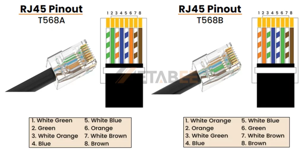
Ethernet cables are terminated according to two wiring standards: T568A and T568B. These standards specify how the eight wires inside the cable connect to the RJ45 pins. Among them, T568B is the most popular choice in modern networks. The following diagrams show the RJ45 pinout and wire color order for both T568A and T568B standards.
RJ45 Pinout T568A and T568B Wiring Diagram
PoE Ethernet Pinout Diagram Based on T568B Standard
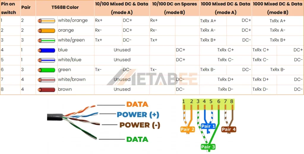
When we talk about the PoE pinout RJ45 configuration, we are looking at how the PSE injects voltage into these specific pins. For 10/100 Mbps data, pairs 4-5 and 7-8 are often “spare” and used for power. However, in Gigabit Ethernet, all four pairs are used for data, meaning power must be “superimposed” on the data-carrying wires.
Expert Note: When crimping, always use modular plugs designed for the specific wire gauge (AWG) of your cable. If the wire is too thin for the contact, the “bite” into the copper will be weak, leading to high electrical resistance—a common cause of PoE device reboots.
PoE Power Modes: Mode A vs. Mode B Explained
PoE systems use two common pinout configurations to deliver power through an Ethernet cable: Mode A and Mode B. Each mode supplies electrical power through different wire pairs inside the RJ45 connector.
Understanding these two modes helps engineers and installers correctly design PoE networks and troubleshoot power delivery issues.
Mode A (Data Pair Power)
Mode A delivers power through the same wire pairs that carry Ethernet data. It uses the following pins:
- Pin 1 and Pin 2
- Pin 3 and Pin 6
These pins normally transmit data in 10/100Base-T Ethernet networks. In Mode A, PoE technology sends power over the same pairs using a method called phantom power, which allows power and data to travel simultaneously without interfering with each other.
Mode A is widely used in PoE switches, because it integrates easily with existing Ethernet switching hardware.
Key characteristics of Mode A:
- Commonly used by PoE switches (PSE devices)
- Compatible with standard Ethernet data transmission
- Often used in modern PoE network deployments
Mode B (Spare Pair Power)
Mode B delivers power through the wire pairs that are not used for data transmission in traditional 10/100 Mbps Ethernet networks. It uses:
- Pin 4 and Pin 5
- Pin 7 and Pin 8
Since these pairs normally remain unused in Fast Ethernet connections, Mode B can dedicate them entirely to power delivery.
Mode B often appears in PoE injectors or midspan power devices, especially in earlier PoE implementations.
Key characteristics of Mode B:
- Power uses the spare wire pairs
- Often used by PoE injectors
- Common in some legacy PoE installations
- Simple to implement in midspan power equipment
| Feature | Mode A | Mode B |
| Power Pairs | 1, 2, 3, 6 | 4, 5, 7, 8 |
| Wire Pairs Used | Data pairs | Spare pairs |
| Polarity | Positive on pins 1 & 2, Negative on pins 3 & 6 | Positive on pins 4 & 5, Negative on pins 7 & 8 |
| Data Transmission | Power and data share the same pairs | Power uses unused pairs in 10/100 Ethernet |
| Common Power Source | PoE switches | PoE injectors |
| Typical Usage | Modern PoE network devices | Some injectors and legacy deployments |
In addition to the power delivery modes, PoE standards such as IEEE 802.3af, 802.3at, and 802.3bt also define the maximum power levels, power negotiation process, and wiring configurations used for Ethernet power transmission.
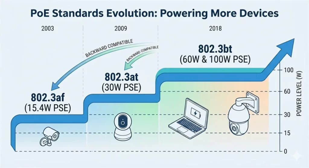
PoE Standards Evolution: 802.3af, 802.3at, and 802.3bt
The history of PoE is a story of increasing power demands. As devices became more powerful (moving from simple phones to motorized PTZ cameras), the poe standard had to evolve. Each new iteration increases the available power levels while maintaining backward compatibility.
| Feature / Standard | 802.3af | 802.3at | 802.3bt | 802.3bt |
| PoE Type / Common Name | Type 1 (PoE) | Type 2(PoE+) | Type 3 (PoE++) | Type 4 (High-Power) |
| Standard Release | 2003 | 2009 | 2018 | 2018 |
| PSE Max Power | 15.4W | 30W | 60W | 90W |
| PD Min Power | 12.95W | 25.5W | 51W | 71.3W |
| Max Current per Pair | 350 mA | 600 mA | 600 mA | 960 mA |
| Cable Pairs Used | 2-pair | 2-pair | 4-pair | 4-pair |
| Supported Ethernet | 10/100/1000 | 10/100/1000 | 2.5G/5G/10G | 2.5G/5G/10G |
| Cable Type (Min) | Cat3 | Cat5 | Cat5e | Cat5e |
| Typical Applications | VoIP phones, basic sensors | Alarm systems, dual-band APs | Video conferencing, building mgmt | Laptops, LED lighting, Flat screens |
The 802.3af power over ethernet poe was the pioneer, providing enough juice for basic devices. However, the 802.3af vs 802.3at debate ended quickly as high-resolution cameras and Wi-Fi 6 access points demanded more than 15 watts.
Today, the 802.3bt pinout is the gold standard for high-power applications. Unlike the older standards that used only two pairs for power, 802.3bt utilizes all four pairs of the Ethernet cable to reach poe power levels of up to 90W.
IEEE 802.3bt supports Cat 5e infrastructure in theory. However, Type 4 deployments face physical limits. Most Cat 5e cables use thin 24 AWG conductors. These wires have high Direct Current Resistance (DCR) at 960 mA. Long 100-meter runs cause large voltage drops. Heat also builds up quickly inside cable bundles. High-power 90W applications require Cat 6a cabling. These cables use thicker 23 AWG solid copper. This is the industrial mandate for thermal safety and signal integrity.
Active vs Passive PoE
Mixing Active vs. Passive PoE can be a dangerous mistake. You must check your device specifications before plugging them in.
Active PoE is smart. It performs a handshake. The PSE checks the device before sending any power. This makes the Active PoE vs. Passive PoE choice the safest option for offices.
Passive PoE is “always on.” So, what is Passive PoE? It sends power immediately without checking the device. If you use a 24V Passive PoE pinout on the wrong device, it will burn the circuits. In the Passive vs. Active PoE debate, professionals choose Active for safety.
Active PoE vs Passive PoE Comparison
| Feature | Active PoE (IEEE Standard) | Passive PoE (Non-Standard) |
| Standard | Follows IEEE 802.3af / 802.3at / 802.3bt | No IEEE standard |
| Handshake Protocol | Yes. Switch detects device before sending power | No, Power is always on |
| Voltage | Regulated voltage, typically 44-57V DC | Fixed voltage, commonly 24V or 48V DC |
| Safty | High. Only supplies power to compatible devices | Lower. May damage non-PoE devices |
| Power Output | Regulated voltage, typically 44-57V DC | Fixed voltage, commonly 24V or 48V DC |
| Power Control | PSE can cut power if PD is disconnected or faulty | Power always on, until manually disconnected |
| Compatibility | Works with standard PoE devices (PD) | Only works with matched devices |
| Cost | Higher | Lower |
Specific brands like MikroTik or older Ubiquiti gear commonly use Passive PoE. When choosing between passive poe vs active poe, you should primarily consider cost and specific hardware requirements. If you use a 24v passive poe pinout, ensure your device explicitly supports that voltage to prevent damage. In most commercial installations, professionals typically choose Active PoE because its handshake protocol provides a safer power delivery method.
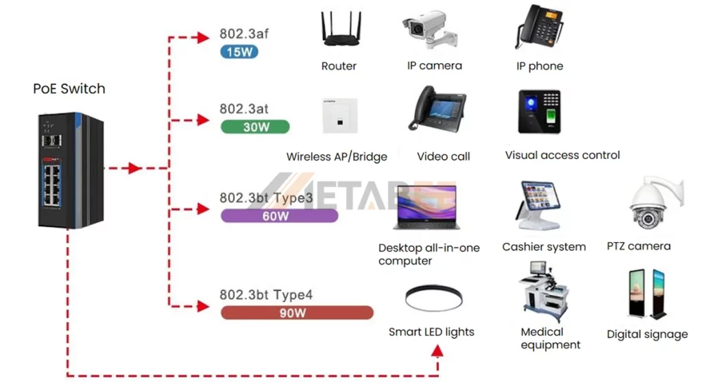
The Most Common Types of PoE Applications
Knowing which connector you need is step one; ensuring you get a high-quality component is step two. Poorly made plugs can lead to signal loss or installation headaches. Here is a quick guide to selecting the right version of each.
PoE is everywhere today. It powers everything from security tools to smart lighting.
- IP Surveillance: If you are asking what is poe camera technology, it’s the ability to run a 4K, night-vision, motorized camera with just one cable. PoE+ (802.3at) is generally required for cameras with heaters or blowers for outdoor use.
- VoIP Phones: The original PoE application. A single cable provides the phone’s connection to the internet and its power.
- Wireless Access Points (WAPs): High-speed Wi-Fi 6 and 7 APs require significant power, often necessitating 802.3at or even 802.3bt.
- Smart Lighting: LED lighting systems are now being powered via PoE, allowing for granular control over brightness and color via the network.
- IoT Sensors: From temperature sensors to occupancy detectors, PoE provides a stable, wired power source that batteries cannot match.
How to Select Cables and Connector for High-Power PoE++?
High-power PoE requires better cables. Thinner cables can melt or drop voltage. The 802.3bt (PoE++) standard enables Ethernet networks to deliver much higher power. As a result, choosing the right cables and wiring standards becomes critical. Proper selection ensures stable power delivery, reliable data transmission, and long-term performance. When deploying high-power PoE++ systems, consider the following factors.
- Cable Category: Cat5e cables support basic PoE deployments. However, high-power PoE++ systems (60W–100W) require Cat6 or Cat6A cables. These cables use thicker copper conductors with a lower gauge, which reduces resistance and heat buildup.
- Conductor Material: Avoid CCA (Copper Clad Aluminum) cables at all costs. PoE generates heat. CCA cables have higher resistance and can melt or cause fires when subjected to high-wattage PoE. Always use 100% Solid Copper cables.
- Heat Dissipation: When many PoE cables are bundled together, heat can rise. In high-power 802.3bt installations, try to keep cable bundles small to allow for better airflow.
- Connector Quality: Ensure your PoE pinout rj45 terminations are clean. High resistance at a poor crimp point can lead to arcing and connector failure under high load.
Conclusion
Mastering the PoE pinout and navigating the PoE standards chart represent the bedrock of modern network deployment. Whether you are integrating legacy 802.3af PoE hardware or deploying cutting-edge, high-power 802.3bt devices, prioritize safety and high-performance cabling to ensure long-term reliability. Do you need expert advice on your network infrastructure? Contact Metabee network specialists to secure a custom, reliable hardware solution tailored to your exact requirements.
Related Product
FAQs
Q1: What is the standard PoE voltage?
A: Most active PoE standards (802.3af/at) operate between 44V and 57V DC. Passive poe is commonly found in 24V or 48V variations.
Q2: Can I plug a non-PoE device into a PoE switch?
A: If the switch is an active PoE switch (802.3af/at/bt), yes. The switch will perform a handshake, realize the device doesn’t need power, and only send data. However, never plug a non-PoE device into a passive PoE injector.
Q3: What is a PoE injector and when should I use one?
A: A 802.3bt PoE injector (or any PoE injector) is a device used to add PoE capability to a non-PoE network link. You use it when you have a standard network switch but need to power a single PoE device like a camera or access point.
Q4: How far can PoE travel?
A: The standard limit for an Ethernet cable is 100 meters (328 feet). This applies to both data and power. Beyond this, you will need a PoE extender or a fiber-to-PoE media converter.
Q5: When should you use PoE?
A: You should use PoE (Power over Ethernet) when a device needs both power and network connectivity but installing a separate power cable is inconvenient.
Q6: How do I know if my device is active or passive poe?
A: Check the manufacturer’s datasheet. If it mentions “IEEE 802.3af/at/bt,” it is active. If it only lists a fixed voltage like “24V DC,” it is likely passive.
Finally, a clear breakdown of active vs passive PoE! I once fried a costly IP camera because someone used a ‘dumb’ passive injector. The handshake protocol explanation is a lifesaver for our junior techs.
Pingback: SFP vs RJ45: What are the Differences and How to Choose - MetabeeAI