In the world of data storage and peripheral connectivity, SCSI carries as much historical weight. This interface was the gold standard for high-performance servers and workstations for decades. While modern interfaces such as SATA and USB dominate today, SCSI remains a critical component in industrial automation, legacy server maintenance, and high-end niche computing.
This guide covers the essentials of SCSI connectors, including their definition, evolution, key features, and role in SCSI bus architecture. It also examines pinouts, signaling methods, and connector types and compares SCSI with modern interfaces.
- Introduction
- Understanding SCSI Pinouts
- SCSI Connector Types
- DB25 (25-pin SCSI Connector)
- Centronics 50 (CN50 – 50-pin, Low Density)
- High-Density DB50 (HD50 – 50-pin, High Density)
- High-Density DB68 (68-pin, High Density)
- VHDCI (Very High-Density Cable Interconnect-68-pin)
- Other Pin Counts (14-pin, 20-pin, 26-pin, 28-pin, 36-pin, 40-pin, 100-pin)
- Quick Comparison Table
- SCSI Specifications
- SCSI vs Modern Interfaces
- Conclusion
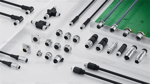
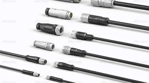
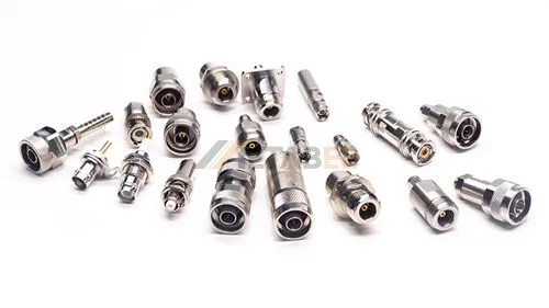
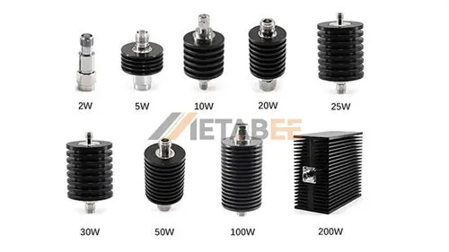
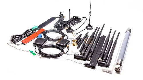
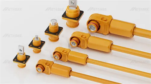
- Related Products
- FAQ
Introduction
What is SCSI?
SCSI, pronounced “skuzzy,” stands for Small Computer System Interface. It is a set of American National Standards Institute (ANSI) standards for physically connecting and transferring data between computers and peripheral devices. Originally developed in the 1980s, SCSI was a dominant interface for connecting hard disk drives, tape drives, CD-ROM drives, scanners, and printers. SCSI was engineered to be a parallel interface that could connect multiple peripherals to a single bus, offering high performance and flexibility for its time.
Evolution of SCSI Standards
The SCSI standard has undergone numerous revisions and enhancements over its lifespan, progressively increasing data transfer rates and device support.
Key evolutionary stages include:
- SCSI-1 (1986): The initial standard, offering 8-bit parallel data transfer at up to 5 MB/s.
- SCSI-2 (1994): Introduced “Fast SCSI” (10 MB/s) and “Wide SCSI” (16-bit, 20 MB/s), along with new command sets and connector types.
- SCSI-3 (1995-2000s): A family of standards that modularized SCSI. This era saw the introduction of Ultra SCSI (20 MB/s), Ultra Wide SCSI (40 MB/s), Ultra2 SCSI (LVD, 80 MB/s), and Ultra3/Ultra160 SCSI (160 MB/s). It also laid the groundwork for serial implementations like Fibre Channel and SSA, and later, SAS.
- Ultra320 SCSI (2002): The fastest parallel SCSI standard, achieving 320 MB/s.
- Serial Attached SCSI (SAS): While not a parallel SCSI standard, SAS is the serial evolution of SCSI, maintaining the SCSI command set while leveraging a serial physical layer for increased speed, scalability, and hot-plug capabilities, often replacing traditional parallel SCSI in enterprise environments.
SCSI Standards Chart
| Standard Version | Release Time | Interface Type | Max Transfer Rate |
|---|---|---|---|
| SCSI-1 | 1986 | Parallel | 5 MB/s |
| SCSI-2 | 1994 | Parallel | 20 MB/s |
| SCSI-3 | 1995-2000s | Parallel | 160 MB/s |
| Ultra320 SCSI | 2002 | Parallel | 320 MB/s |
| Serial Attached SCSI (SAS) | Serial evolution | Serial | Much higher than parallel SCSI |
Why It Matters
SCSI’s significance stems from its foundational role in enterprise computing and high-performance applications.
- Specific Niche Applications: In environments requiring high reliability, long cable lengths, or specific command set functionalities, SCSI-based solutions may still be encountered.
- Legacy System Management: Many industrial, medical, and specialized computing systems still rely on SCSI for their robust and proven architecture.
- Historical Context: It provides essential context for understanding the development of modern storage interfaces and protocols, including SAS.
What is an SCSI Connector?
Definition
An SCSI connector is a physical hardware interface that connects SCSI devices to a computer’s host controller or to other SCSI devices within a daisy-chain configuration. It carries the parallel bus signals that implement the SCSI communication standard.
At its core, an SCSI connector is a multi-pin electrical connector designed to carry differential or single-ended SCSI signals. The number of pins, their arrangement, and the connector’s physical form factor vary significantly across different SCSI standards and device types. Their primary role is to establish a reliable physical link for the SCSI bus, ensuring proper electrical contact and signal integrity for data transmission.
Common SCSI connector types include Centronics 50 (CN50), DB25, High-Density 50 (HD50), High-Density 68 (HD68), and Very High Density Cable Interconnect (VHDCI).
Key Features
SCSI connectors possess several key features that contribute to the overall SCSI system’s performance and reliability:
- Multi-pin Design: SCSI connectors typically feature a high number of pins (25, 50, 68, etc.) to support parallel data transfer and various control signals.
- Shielding: Most SCSI cables and connectors are well-shielded to prevent electromagnetic interference (EMI) and ensure signal integrity.
- Termination: Proper termination is crucial for SCSI buses. Connectors often integrate or facilitate external termination to prevent signal reflections that can corrupt data.
- Locking Mechanisms: Many SCSI connectors feature latches, clips, or screw-down mechanisms to ensure a secure and stable connection, preventing accidental disconnections in critical applications.
- Pin Pitch and Density: Connectors evolved from larger, lower-density designs to smaller, higher-density variants to conserve space and improve signal characteristics.
How Does SCSI Connector Work?
The functionality of SCSI connectors is intrinsically linked to the SCSI bus architecture, which governs how devices communicate and share the bus.
SCSI Bus Architecture
The SCSI bus operates on a “peer-to-peer” logic. Every device on the bus is assigned a unique SCSI ID. The bus must be terminated at both ends to prevent signal reflection, which would otherwise corrupt data. A parallel SCSI system consists of the following:
- Host Adapter (Initiator): This card or integrated chip in the computer initiates and controls SCSI operations. It has one or more SCSI ports to which devices connect.
- Target Devices: These are the peripherals (hard drives, tape drives, etc.) that respond to commands from the initiator.
- Connectors: Physical interfaces on devices and cables that join them to the bus.
- Terminators: Electronic devices placed at each end of the SCSI bus to absorb electrical signals, preventing reflections and ensuring signal integrity.
Key Technical Concepts
- Single-Ended (SE): Uses a single wire for each signal, with voltage levels referenced to a common ground. Simpler and less expensive, but more susceptible to noise and limited to shorter cable lengths (up to 6 meters).
- Differential (DIFF): Uses two wires for each signal, with the signal being the difference in voltage between the two wires. This method is far less susceptible to noise and allows for much longer cable lengths (up to 25 meters or more). Differential SCSI further evolved into:
- Low-Voltage Differential (LVD): Lower voltage differential signaling allows longer cables and higher speeds. It is the standard for modern, faster SCSI.
- High-Voltage Differential (HVD): Legacy high‑voltage differential used in older systems; incompatible with SE without conversion.
Most modern SCSI systems use LVD signaling. The voltage differential is typically small,
calculated as:
- Termination: SCSI termination power must be present at the bus ends to maintain electrical integrity.
- Bus Width: Refers to the number of data lines. Early SCSI was 8-bit, while Wide SCSI introduced 16-bit data paths, effectively doubling the data transfer rate.
- Clock Speed: Determines how quickly data bits are transmitted across the bus. “Fast” and “Ultra” designations refer to increased clock speeds.
- Daisy Chaining: Multiple SCSI devices can be connected in series, one after another, on a single SCSI bus. Each device on the chain must have a unique SCSI ID.
Comparison of SCSI Signal Types: SE vs. HVD vs. LVD
| Feature | SE (Single-Ended) | HVD (High Voltage Differential) | LVD (Low Voltage Differential) |
|---|---|---|---|
| Signaling Method | Uses a single signal line and a ground line; susceptible to noise and interference | Uses a pair of differential signal lines (high voltage); excellent noise immunity | Uses a pair of differential signal lines (low voltage); excellent noise immunity |
| Max. Cable Length | Short, up to 6m | Longest, up to 25m | Long, 12m |
| Max. Data Rate | Lower, max approx. 40 MB/sec (Ultra Wide mode) | Medium, max approx. 40 MB/sec (Ultra Wide mode) | Very High, supports Ultra2 (80 MB/sec) and beyond, such as Ultra320 (320 MB/sec) |
| Compatibility | Compatible with LVD devices under certain conditions | Incompatible with both SE and LVD. Mixing can damage equipment. | Backward compatible with SE. |
| Characteristics & Application | Used in early SCSI standards. Low cost, but short distance, slow speed, and poor noise immunity. | Used for applications requiring very long distances. High power consumption and cost; largely obsolete, replaced by LVD. | The mainstream standard for modern SCSI. Combines high speed, long distance, low power, and backward compatibility. |
Understanding SCSI Pinouts
SCSI connectors vary significantly in pin count and physical form factor, but they all follow structured mappings for data lines, control signals, grounding, and termination power.
Pinout Diagrams for Common Types
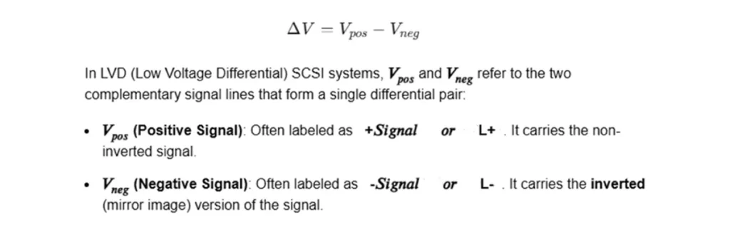
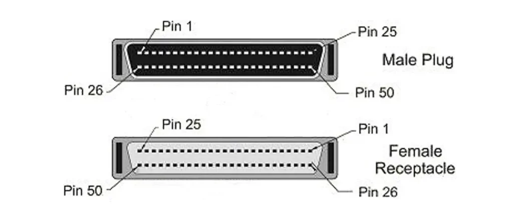
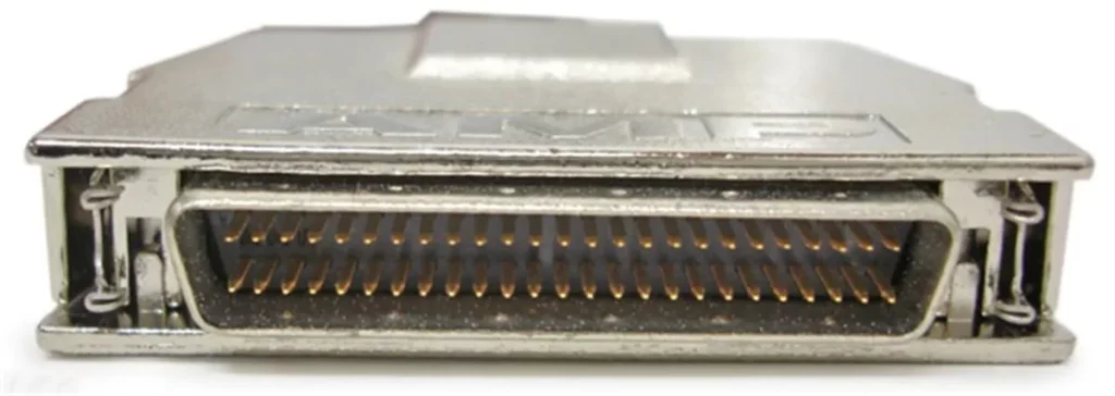
CN50 (Centronics 50-pin)
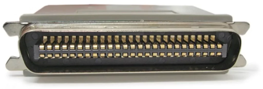
The CN50 connector is the standard external connector for narrow (8-bit) SCSI-1 and SCSI-2 devices. It uses a micro-ribbon (Centronics-style) interface with robust grounding for improved signal integrity.
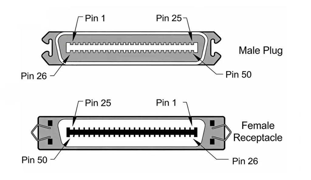
DB25 (25-pin SCSI Connector)
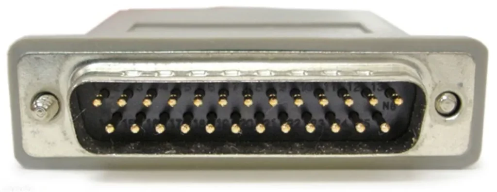
The DB25 connector, often resembling a parallel port, was an early and widespread choice for SCSI-1 implementations, particularly on Apple Macintosh computers and some PCs. It’s 25 pins allowed for an 8-bit narrow SCSI data path.
Related post:
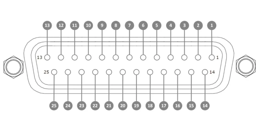
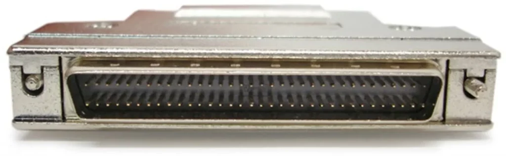
High-Density DB50 (HD50 – 50-pin, High Density)
The HD50 connector supports 8-bit (narrow) SCSI with improved grounding and signal organization. Pins are arranged in two rows, enabling better shielding and higher reliability.
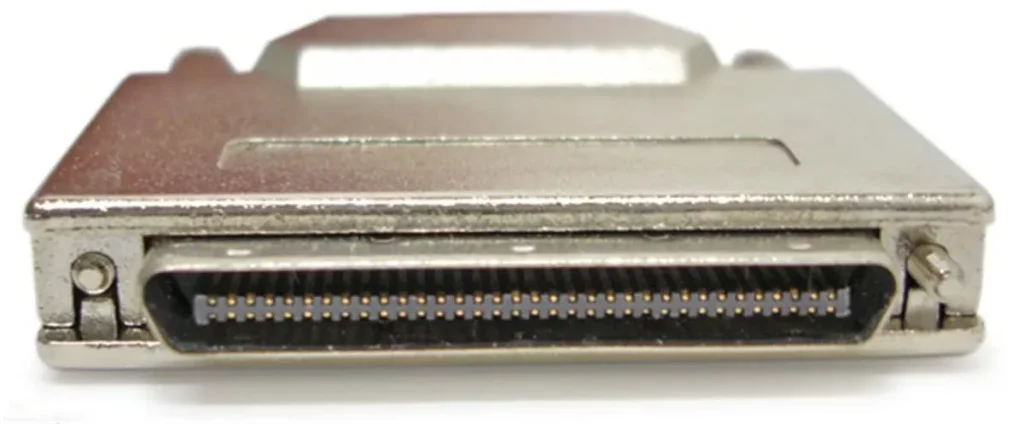
High-Density DB68 (HD68 – 68-pin, High Density)
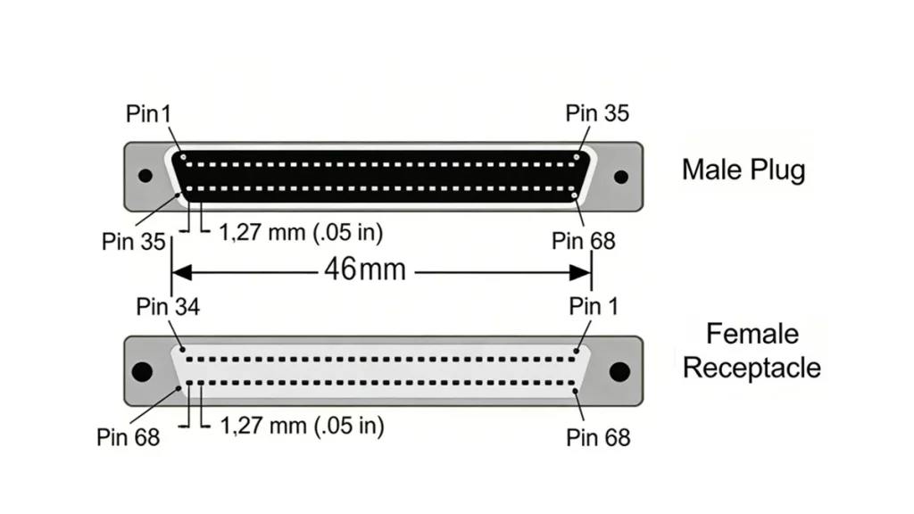
The HD68 connector became ubiquitous with the introduction of Wide SCSI, supporting a full 16-bit data path. It is commonly found in Ultra SCSI, Ultra2 SCSI, and Ultra3 SCSI (also known as Ultra160/Ultra320) systems, especially for internal and external peripheral connections. Its higher pin count accommodates the wider data bus and additional control signals required for faster and more robust communication.
VHDCI (Very High-Density Cable Interconnect-68-pin)
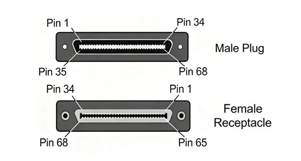
VHDCI is a compact version used in high-performance SCSI systems and is very small in size. It maintains a 68-pin configuration, supporting a 16-bit-wide data path.
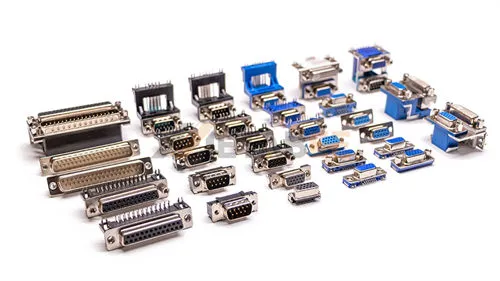
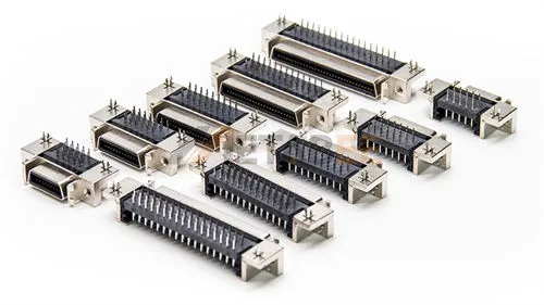
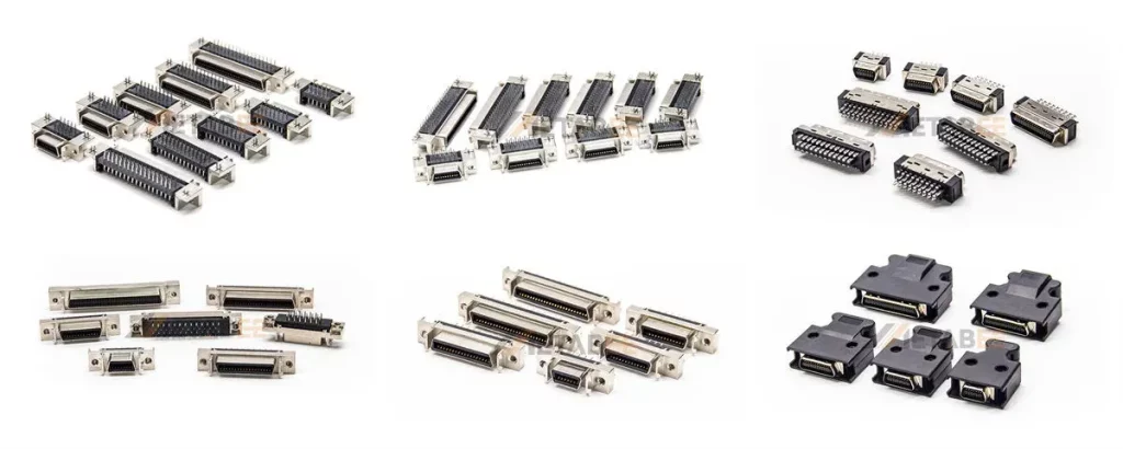
SCSI Connector Types
The evolution of SCSI standards led to a proliferation of connector types, each designed to support different speeds, bus widths, and form factors.
Metabee offers a comprehensive range of high-quality SCSI connectors:
DB25 (25-pin SCSI Connector)
Centronics 50 (CN50 – 50-pin, Low Density)
High-Density DB50 (HD50 – 50-pin, High Density)
High-Density DB68 (68-pin, High Density)
VHDCI (Very High-Density Cable Interconnect-68-pin)
Other Pin Counts (14-pin, 20-pin, 26-pin, 28-pin, 36-pin, 40-pin, 100-pin)
Quick Comparison Table
| Connector Type | Also Known As | Pin Count | Bus Width | Common Standards / Speed |
|---|---|---|---|---|
| DB25 | Apple SCSI, SCSI-1 | 25-pin | Narrow (8-bit) | SCSI-1 (up to 5 MB/s) |
| Centronics 50 | CN50, Low-Density 50, Old Style | 50-pin | Narrow (8-bit) | SCSI-1, SCSI-2 (up to 5 MB/s) |
| High-Density DB50 | HD50, Mini DB50, Micro DB50 | 50-pin | Narrow (8-bit) | SCSI-2 Fast (up to 10 MB/s) |
| High-Density DB68 | HD68, Mini DB68, Micro DB68 | 68-pin | Wide (16-bit) | SCSI-3, Ultra, Ultra2 (up to 80 MB/s) |
| VHDCI | Very High-Density Cable Interconnect | 68-pin | Wide (16-bit) | Ultra160, Ultra320 (up to 320 MB/s) |
SCSI Specifications
To summarize the performance characteristics related to SCSI, here are the main specifications across different parallel SCSI standards:
| SCSI Standard | Bus Width | Max Speed | Max. Devices | Max Cable Length | Signaling Type |
|---|---|---|---|---|---|
| SCSI-1 | 8-bit | 5 | 8 | 6m | Single-Ended |
| Fast SCSI | 8-bit | 10 | 8 | 3m | Single-Ended |
| Fast Wide SCSI | 16-bit | 20 | 16 | 3m | Single-Ended |
| Ultra SCSI | 8-bit | 20 | 8 | 1.5m | Single-Ended |
| Ultra-Wide SCSI | 16-bit | 40 | 16 | 1.5m | Single-Ended |
| Ultra2 SCSI | 8-bit | 40 | 8 | 12m | LVD |
| Ultra2 Wide SCSI | 16-bit | 80 | 16 | 12m | LVD |
| Ultra3 / Ultra160 | 16-bit | 160 | 16 | 12m | LVD |
| Ultra320 SCSI | 16-bit | 320 | 16 | 12m | LVD |
SCSI vs Modern Interfaces
While parallel SCSI dominated enterprise storage for many years, modern interfaces have largely taken over due to advancements in serial communication, cost-effectiveness, and ease of use.
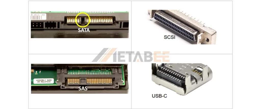
SCSI vs SATA
SCSI (Parallel SCSI): The SCSI is a parallel bus architecture that supports multiple devices on a single cable, delivering performance up to 320 MB/s. It is more expensive. SCSI offers advanced features, longer cable distances via differential signaling, and high reliability, using multi-pin connectors like CN50, HD68, and VHDCI.
SATA (Serial ATA): It uses a point-to-point serial architecture, allowing one device per port and delivering speeds up to 600 MB/s. It is a cost-effective solution. SATA also supports hot-swapping and easy configuration, using 7-pin data and 15-pin L-shaped power connectors. SATA drives are not directly compatible with SCSI/SAS controllers.
SCSI vs SAS
SAS (Serial Attached SCSI): SAS is the modern evolution. It uses the SCSI command set but transmits data serially. And It features a point-to-point serial architecture with expanders and supports thousands of devices. It delivers up to 22.5 Gbps per lane (SAS-4), reaching 90 Gbps with four lanes. SA offers backward compatibility with SATA drives, using compact L-shaped connectors with higher pin counts for multi-lane performance.
SCSI vs USB
USB (Universal Serial Bus): USB is a highly versatile interface used across a wide range of peripherals, including storage, input, audio, video, and networking devices. It delivers performance ranging from 1.5 Mbps (USB 1.0) up to 40 Gbps (USB4), while offering plug-and-play simplicity. USB also supports power delivery and hot-plugging as standard features, using a variety of compact connector types such as Type-A, Type-B, Mini, Micro, and Type-C.
Comparison Summary Table
| Specification | Parallel SCSI | SAS | SATA | USB-C |
|---|---|---|---|---|
| Primary Use | Legacy Enterprise | Modern Enterprise | Consumer Storage | Peripherals/External |
| Max Speed | 320 MB/s | 22.5 GB/s (SAS-4) | 600 MB/s | 1.25 GB/s (10 Gbps) |
| Daisy Chaining | Yes | No (Uses Expanders) | No | No (Uses Hubs) |
| Termination | Required Manually | Automatic | Automatic | Automatic |
| Compatibility | SCSI-only | SAS + SATA | SATA-only | – |
Conclusion
The SCSI connector stands as a foundational technology in the evolution of enterprise data storage. It enables reliable communication between hosts and multiple peripherals through a shared bus system. Although modern interfaces such as SATA, SAS, and USB have largely replaced traditional SCSI, its robust architecture, differential signaling, and proven reliability ensure continued relevance in legacy and industrial environments. It continues to power mission-critical systems in industrial automation, medical imaging (MRI/CT), and vintage server maintenance. When selecting a connector, always verify the pin count, density (low vs. high), and signaling type (SE vs. LVD) to ensure compatibility.
For more information about Metabee SCSI connector products or for professional consultation, please feel free to contact us
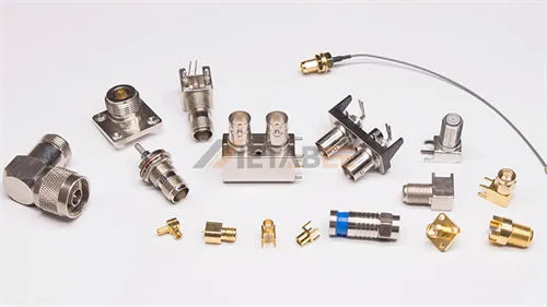
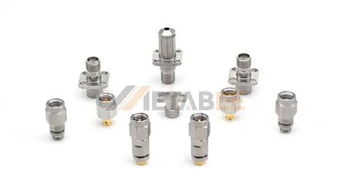
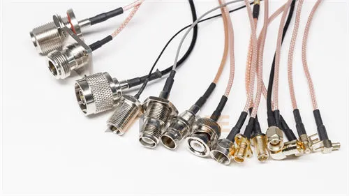
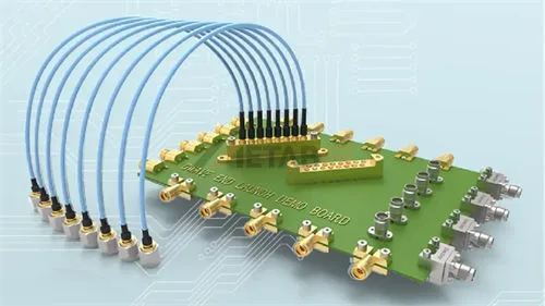
Related Products
FAQ
Q1: What is an SCSI connector used for?
A: An SCSI connector is primarily used to interface storage and peripheral devices with a host system. It enables multiple devices to share a single bus, making it highly efficient for enterprise and legacy computing environments.
Q2: How many devices can be connected to an SCSI bus?
A: A standard SCSI bus can support multiple devices connected in a daisy-chain configuration. Traditional narrow SCSI supports up to 7 devices, while wide SCSI configurations can support up to 16 devices. Each device is assigned a unique SCSI ID to ensure proper communication.
Q3: What is a SCSI ID?
A: A SCSI ID is a unique numerical address (0-7 for 8-bit SCSI, 0-15 for 16-bit Wide SCSI) assigned to each device on a parallel SCSI bus. The host adapter usually takes ID 7. Each device must have a distinct ID for the system to identify and communicate with it correctly.
Q4: Can I connect a 50-pin device to a 68-pin controller?
A: Yes, using a “Wide-to-Narrow” adapter. However, the bus will default to the speed of the slowest device.
Q5: Do I need to terminate a SCSI bus?
A: Yes, proper termination is crucial for parallel SCSI buses. Terminators must be placed at both physical ends of the bus to prevent signal reflections that can cause data corruption and system instability. Without correct termination, the SCSI bus will not function reliably.
Q6: What is the main difference between internal and external SCSI connectors?
A: Internal SCSI connectors are unshielded and designed for connecting devices within a computer case. External SCSI connectors are shielded and use more robust locking mechanisms for connecting peripherals outside the case, often allowing for longer cable runs.
Q7: Do all SCSI connectors support differential signaling?
A: No, connectors like DB25 generally do not support differential; HD68 or VHDCI with LVD support is required.
Q8: What is the maximum cable length for an SCSI connector?
A: The maximum length depends on the signaling type:
Single-Ended (SE): Up to 6 meters.
LVD (Low-Voltage Differential): Up to 12 meters for multiple devices.
HVD (High-Voltage Differential): Up to 25 meters.
Q9: How does SCSI compare to modern interfaces like SATA or USB?
A: SCSI differs significantly from modern interfaces:
- SCSI: Multi-device bus architecture, high reliability, enterprise-oriented
- SATA: Point-to-point architecture, simpler and widely used in consumer storage
- USB: Universal, plug-and-play interface for general peripherals
Q10: Why Choose Metabee SCSI Connector
A: As a specialized connector manufacturer, Metabee offers more than just hardware. We provide independently developed, customizable interconnect solutions backed by professional technical support, factory-direct pricing, and premium-grade materials that ensure long-term durability in enterprise environments.