Many WiFi signal problems are not caused by poor router performance, but by using the wrong antenna connector type. WiFi antenna connector types matter more than most users expect. SMA and RP-SMA look very similar, so users often assume they are compatible. This leads to buying the wrong antenna, resulting in cases like “it fits but there is no signal” or “it cannot be installed at all.” In addition, there are many connector types such as N-Type, U.FL, and MHF4. Beginners often find it difficult to quickly identify which connector their device needs.
This guide will explain common WiFi antenna connector types, including SMA, RP-SMA, N-Type, U.FL IPEX, MHF4, MCX/MMCX, and TNC. You will learn how to identify different connectors by thread structure and center pin design. You will also understand the typical applications of each type and how to choose the right antenna cable and adapter. This helps you avoid compatibility mistakes and unnecessary signal loss.
Introduction
What is a WiFi Antenna?
A WiFi antenna is a device that converts electrical signals into electromagnetic waves and enables wireless communication. Most WiFi antennas operate in the 2.4 GHz and 5 GHz frequency bands. In WiFi 6E and WiFi 7 applications, operation also extends to the 6 GHz band, supporting higher bandwidth and lower interference communication environments.
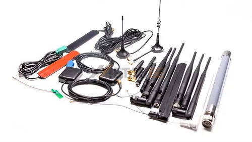
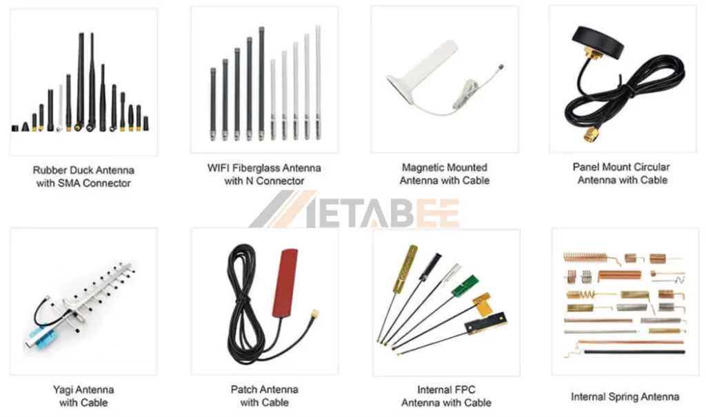
WiFi antennas come in many physical forms. They can be rubber duck antennas, magnetic mount antennas, panel antennas, or internal FPC and PCB antennas, depending on the device design and installation requirements. These antennas are widely used in routers, access points, laptops, and IoT devices. Different application scenarios require different antenna types. Omnidirectional antennas provide wide coverage, while directional antennas support long-distance transmission.
What is a WiFi Antenna Connector?
A WiFi antenna connector is the mechanical and electrical interface between the antenna and the RF device. It ensures stable signal transmission while keeping impedance matched, usually at 50 ohms.
The connector type affects compatibility, signal loss, durability, and whether the antenna can be replaced or upgraded.
Two Main Categories
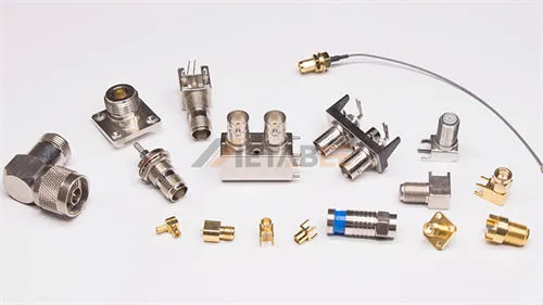
WiFi antenna connectors generally fall into two distinct mechanical categories based on their application:
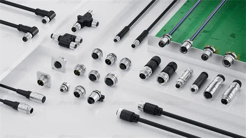
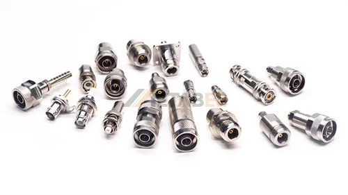
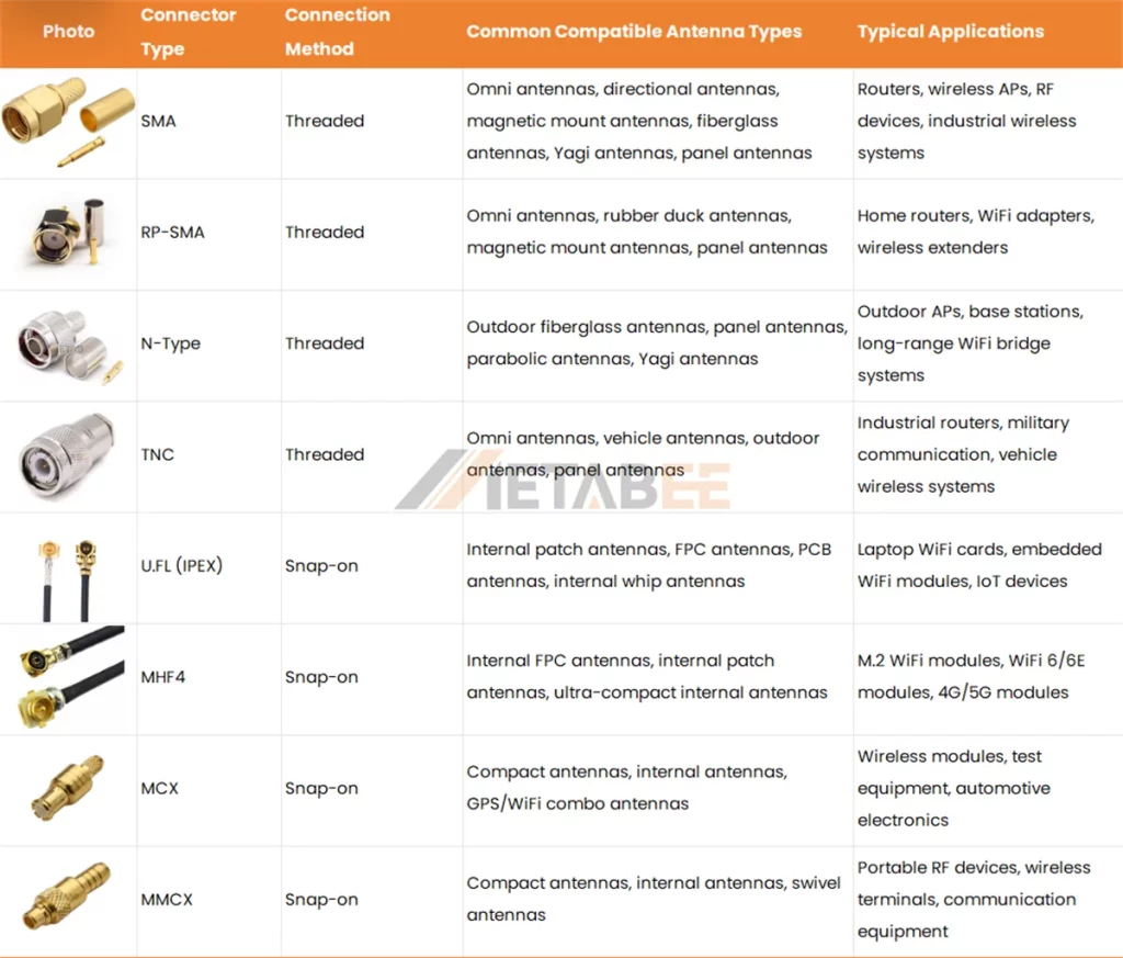
- Threaded/Ruggedized Connectors: This category includes SMA, RP-SMA, N-Type, and TNC interfaces. These connectors feature heavy-duty screw-on housings designed for durability. They offer a secure, vibration-resistant path for RF signals in environments where the cable may be exposed to the elements or frequent handling.
- Push-Fit/Micro-Connectors: This category includes U.FL (IPEX), MHF4, MCX/MMCX, and TS9 interfaces. These are ultra-miniature RF interfaces designed for space-constrained interiors. They utilize a “snap-on” mating style to maintain a low profile inside compact hardware. Because of their delicate design, they are not intended for frequent disconnection.
WiFi Antenna Connector Types and Typical Antenna Applications
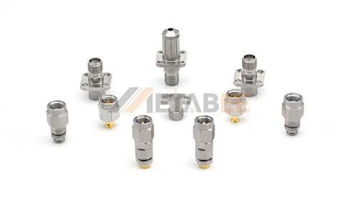
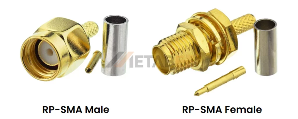
SMA and RP-SMA Connector
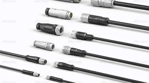
SMA and RP-SMA connectors are the most widely used RF connectors in WiFi systems. They are commonly found on WiFi routers, wireless adapters, antennas, access points, and outdoor CPE devices. Their popularity comes from their compact size, stable performance, and threaded locking design.
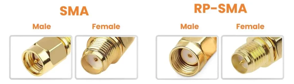
However, SMA and RP-SMA are not interchangeable. Many users confuse them because they look almost identical. The key difference is the center contact structure, which affects compatibility.
What is an SMA Connector
The SMA connector (SubMiniature version A) is a 50-ohm coaxial RF interface engineered for high-frequency signal transmission. Developed in the 1960s, it utilizes a 1/4-36 threaded coupling to ensure vibration-resistant, low-loss connections up to 18 GHz. Due to its superior mechanical strength and signal stability, SMA is the industry standard for external wifi antenna systems, cellular radio, and aerospace applications.
What is an RP-SMA Connector
The RP-SMA connector (Reverse Polarity SMA) is the most common interface found on consumer-grade wireless hardware. The development of this standard was driven by regulations requiring that users not easily replace antennas with unauthorized high-gain alternatives. By swapping the gender of the center pin and receptacle, manufacturers created a “proprietary” feel for consumer hardware.
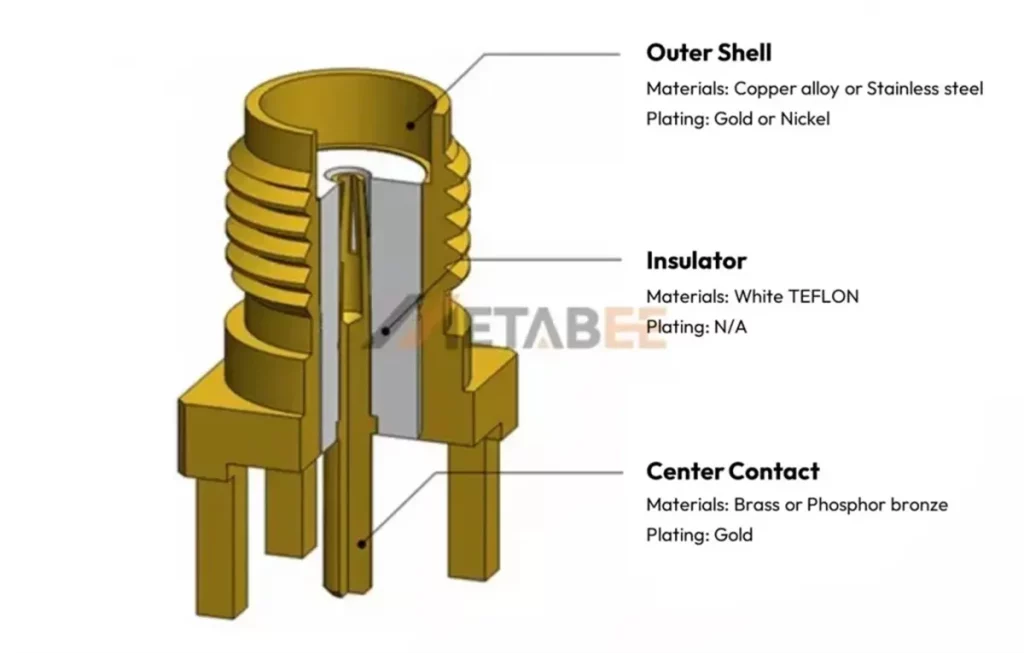
SMA Connector Materials and Structure
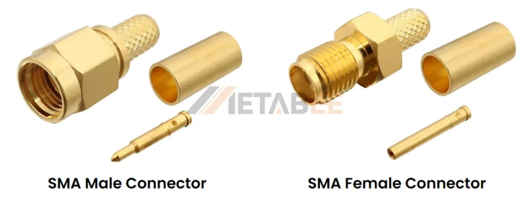
The SMA connector features a threaded 1/4-36 coupling that utilizes an outer shell made of copper alloy or stainless steel. Inside the shell, a gold-plated brass or phosphor bronze center contact ensures reliable signal transmission. A white Teflon insulator separates these components to maintain stable 50-ohm impedance.
Electrical Specifications
While SMA and RP-SMA connectors differ in gender and pin polarity, they share identical electrical characteristics.
| Specification | Typical Rating / Value |
| Impedance | 50 Ω |
| Frequency Range | DC to 18 GHz (optimized) |
| VSWR (Voltage Standing Wave Ratio) | ≤ 1.25 (at 18 GHz) |
| Working Voltage | 500 V (RMS) |
| Dielectric Withstanding Voltage | 1,000 V (RMS, at sea level) |
| Contact Resistance | Center: ≤ 3.0 mΩ / Outer: ≤ 2.0 mΩ |
| Insulation Resistance | ≥ 5,000 MΩ |
| RF Leakage | -60 dB min (at 2-3 GHz) |
Related Post: SMA vs RP-SMA: Key Differences, Compatibility & How to Choose the Right Connector
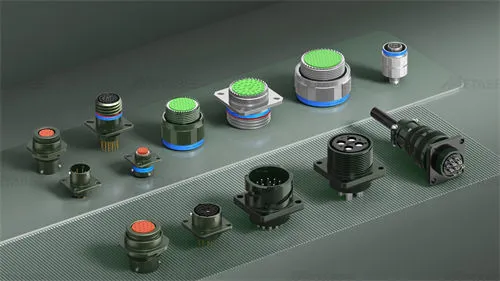
N-Type Connector
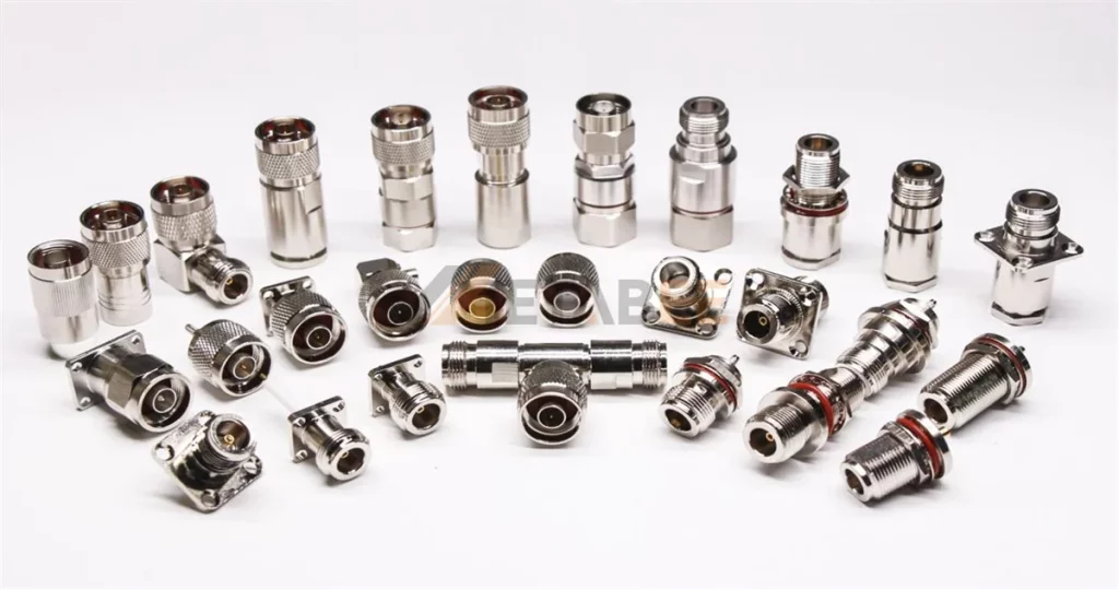
The N-Type connector is a medium-threaded RF connector commonly used as an outdoor Wi-Fi antenna connector. It has a robust metal body and a screw-on coupling design that keeps the connection stable in harsh environments. Engineers often choose N-Type for outdoor WiFi antennas because it supports low-loss transmission and handles long-term exposure to rain, dust, and vibration.
Key features and characteristics:
- Threaded coupling mechanism
- 50 Ohm impedance
- Higher frequency range (DC to 11 GHz )
- Robust and weatherproof construction
- Medium-sized
- More robust and stable connection
The N-type connector is not just one interface but a family of connectors designed for high-power, low-loss RF performance. When selecting an n type antenna connector for your WiFi deployment, you must distinguish between two primary variants to avoid critical impedance mismatches.
- 50-Ohm N-Type: This is the standard for nearly all wireless communication. It is the perfect match for WiFi antennas, cellular base stations, and industrial RF cabling.
- 75-Ohm N-Type: This variant is designed for high-end cable TV (CATV) and broadcast video. They look almost identical to the 50-ohm version, but the internal center pin is thinner.
Note: If you accidentally mate a 75-ohm N-Type connector with a 50-ohm device, you create a major impedance mismatch. This causes signal reflection, power loss, and potential damage to your WiFi radio’s power amplifier.
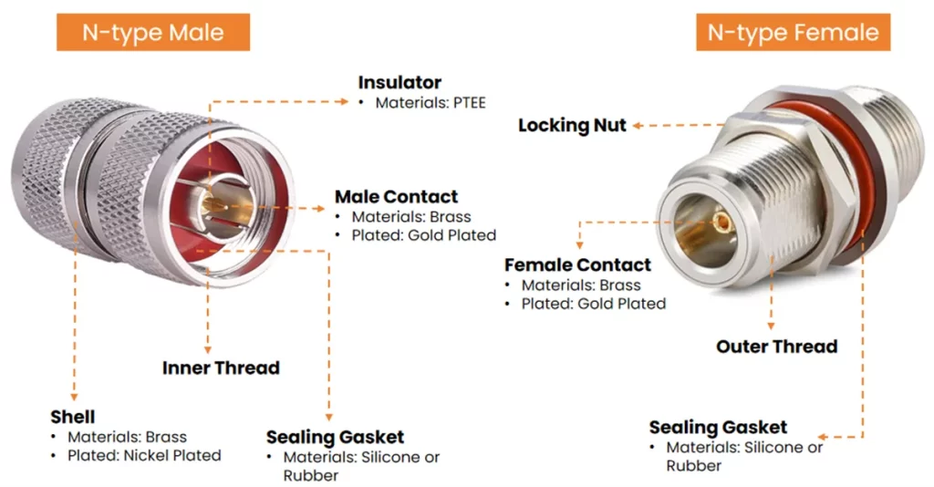
Structure and Materials
Related Post: What is an N-type connector? A Deep Dive into its Specifications, Dimensions, Types, and Selection Tips
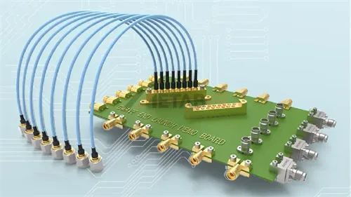
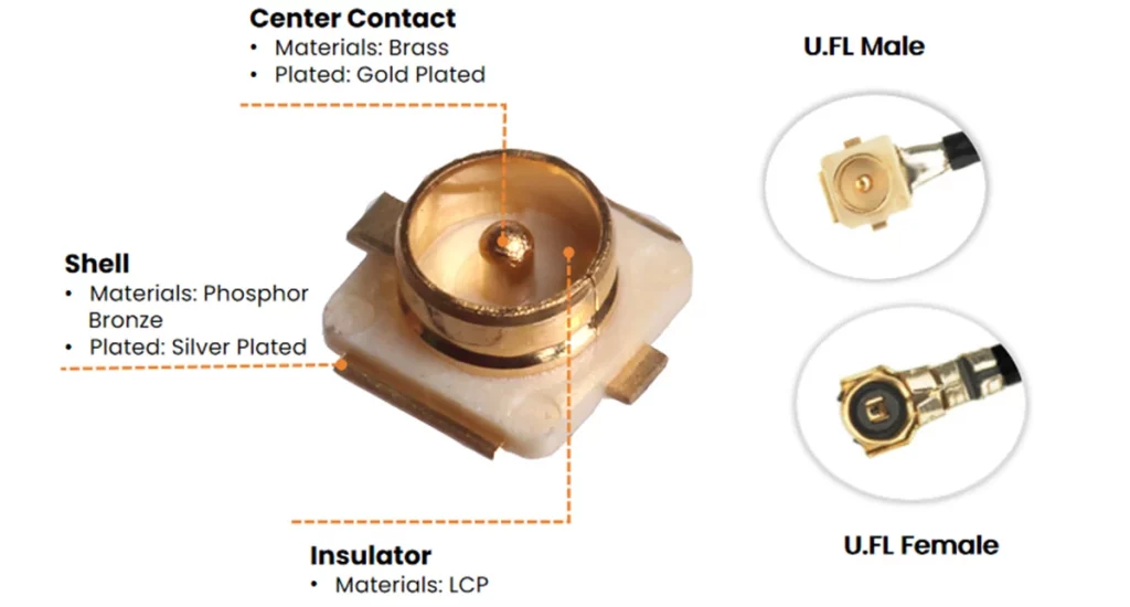
U.FL Connectors(IPEX)
U.FL (also known as IPEX) serves as a miniature snap-on RF connector. Hirose originally defined the U.FL specification, while IPEX denotes the compatible MHF series. Because these standards share identical physical and electrical profiles, engineers frequently use the terms interchangeably. These interfaces solve the challenge of installing external connectors on compact PCBs, making them essential for space-constrained electronics. You commonly find these connectors in laptop WiFi cards, embedded wireless modules, and IoT devices. They typically link to internal FPC antennas, PCB antennas, or miniature whip antennas via thin coaxial cables like RG178. This makes them the ideal choice for lightweight, space-saving designs.
Structure and Materials
MHF4 Connector
The MHF4 connector belongs to the I-PEX MHF ultra-miniature RF series. It is distinct from the traditional U.FL (MHF1) interface. While I-PEX manufactures both series, MHF4 represents a newer generation engineered specifically for extreme miniaturization.
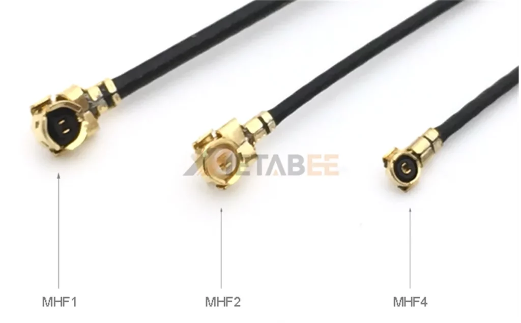
As shown in the figure above, to meet the demands of modern electronic devices, the MHF series has undergone a significant reduction in size. Compared to U.FL (MHF1), MHF4 significantly optimizes PCB real estate. It reduces the PCB footprint by over 50% and offers a 50% lower mating height (approx. 1.2mm). This makes MHF4 the premier choice for ultra-thin wireless modules, such as M.2 WiFi cards and 5G communication hardware. Despite its smaller size, MHF4 maintains a strict 50-ohm impedance and supports high-frequency performance up to 12 GHz+, ensuring robust signal integrity for demanding WiFi 6E and WiFi 7 applications.
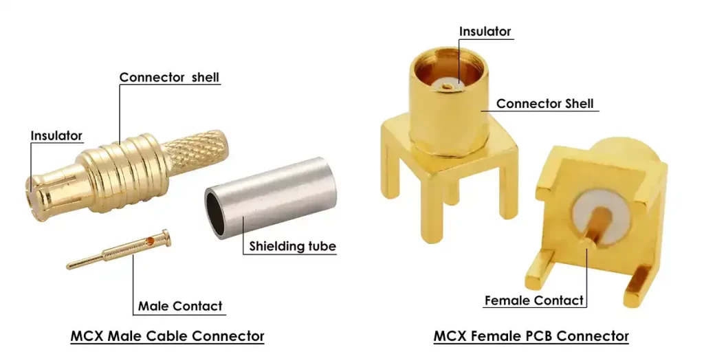
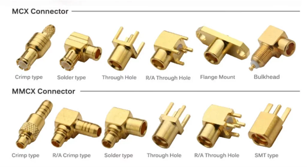
MCX/MMCX Connector
MCX and MMCX are snap-on coaxial RF connectors. They are mainly used in space-constrained applications that require highly reliable signal transmission. Both use a push-on design, so users can connect and disconnect quickly without threading.
MCX connector is larger and offers stronger mechanical stability. MMCX connector is smaller and supports full 360-degree rotation after mating. This feature helps adjust antenna direction without disconnecting the cable.
Key characteristics include:
- Impedance: 50 ohms
- Frequency range: DC to 6 GHz
- Interface type: Snap-on coupling with 360° rotation
- Size: About 2.4 mm (0.095 in) in outer diameter
MCX often appears in automotive systems, RF modules, and test equipment where durability matters more. MMCX fits compact devices like WiFi modules, drones, and wearables where space is limited and antenna flexibility is important.
In selection, MCX works better for stable and rugged environments. MMCX works better for small devices that need flexible antenna positioning.
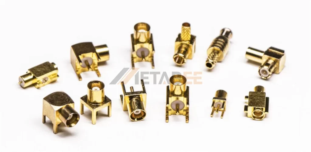
Structure of MCX Connector
MCX and MMCX Connector Types
Related Post: MCX vs MMCX Connector: Key Differences You Must Know and How to Choose
TNC and RP-TNC Connector
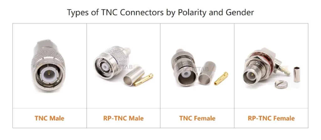
TNC is a threaded RF connector. It commonly works as a WiFi antenna connector in industrial and outdoor wireless systems. Many TNC connectors look similar to BNC, but TNC uses threads instead of a bayonet lock. A TNC female connector uses an external thread with a center socket, while a male connector uses an internal thread with a brass center pin. RP-TNC and TNC use the same threaded structure, but they reverse the center pin and socket. Therefore, RP-TNC antenna connectors cannot mate with standard TNC connectors and cannot form an electrical connection.
Key features and characteristics:
- Threaded Coupling: Ensures a gas-tight, vibration-proof connection in high-stress environments.
- 50-Ohm Precision: Maintains consistent impedance to prevent signal reflection at high frequencies.
- Operating Frequency: Delivers stable RF transmission from DC up to 11 GHz.
- Superior Shielding: The continuous threaded contact minimizes electromagnetic interference (EMI).
- Environmental Sealing: Provides robust protection against moisture, dust, and salt spray.
- Polarity Options: Available in both standard TNC and RP-TNC (Reverse Polarity) configurations.
Related Post: What is a TNC connector? A Detailed Explanation of its Types, Specifications, Applications, and Selection Guide
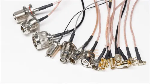
Selecting Wi-Fi Antenna Cables
After selecting the antenna connector, cable choice directly affects signal performance. A Wi-Fi antenna cable uses coaxial structure to carry RF signals while keeping impedance stable at 50 Ω. The right cable improves signal quality and reduces loss.
Cable Types
Common Wi-Fi antenna cables include RG174, RG316, RG178, and LMR series cables.
- RG174 works for general indoor use and short distance connections.
- RG316 handles higher temperature and offers slightly lower loss.
- RG178 supports very thin designs and fits internal connections like U.FL and MHF4.
- LMR series cables focus on low loss and work well for long-distance or outdoor systems.
Thinner cables bend easily but increase signal loss. Thicker cables reduce loss but limit routing flexibility.
Connector and Cable Matching
Cable selection depends on connector size and structure. Each connector supports specific cable diameters and applications.
| Connector Type | Typical Compatible Cables |
|---|---|
| SMA / RP-SMA | RG174, RG316, LMR-100, RG58 |
| N-Type | LMR-400, RG8, RG213 |
| MCX / MMCX | RG174, RG316 |
| U.FL / MHF4 | RG178, RG1.13, 0.81mm |
| TNC / RP-TNC | RG58, LMR-200, LMR-400 |
Selection Factors
Several factors affect cable choice:
- Cable Length: longer cables increase signal loss
- Frequency: higher frequency bands such as 5 GHz and 6 GHz suffer more loss
- Installation Space: tight layouts need thinner cables
- Environment: outdoor or industrial systems need stronger and more stable cables
- Signal Loss Requirement: high-gain systems need low-loss cables
Conclusion
Coaxial antenna connectors play a key role in stable rf signal transmission. each type has its own structure, coupling method, and application scenario. selecting the right connector helps improve system reliability, reduce signal loss, and ensure long-term performance in wireless systems.
Metabee offers a wide range of coaxial antenna connector types, including sma, rp-sma, n-type, tnc, mcx, mmcx, and u.fl solutions. these products are designed to support different frequency bands, installation environments, and device integration needs.
if you need support for selection, customization, or technical guidance, please feel free to contact us. our team can help you choose the right solution for your project.
Related Products
FAQs
Q: Why is “Impedance” (50Ω vs 75Ω) so important?
A: RF equipment is calibrated to 50 ohms. If you use a 75-ohm cable (typically used for Cable TV), the impedance mismatch will cause significant signal reflection, drastically reducing your WiFi range and stability.
Q: How do I identify if my U.FL connection is secure?
A: U.FL connectors should produce a subtle, tactile “click” when seated. If the connector feels loose or rotates easily, it is not properly engaged. For critical installations, use a small dab of RF-safe adhesive to secure the connector against vibration.
Q: What is the main difference between IPEX and U.FL?
A: None. They are essentially the same. U.FL is the original specification name by Hirose, while IPEX (MHF series) is the widely adopted compatible standard. You can use them interchangeably in your designs.
Q: Does cable length affect my WiFi signal?
A: Yes. Every meter of coaxial cable introduces “insertion loss” (measured in dB). Always keep your antenna cables as short as possible. If you need more range, use a higher-gain antenna rather than a longer cable.
Q: What is a TS9 connector?
A: A TS9 connector is a micro-coaxial RF interface primarily designed for 4G/LTE modems and mobile hotspots, not standard WiFi equipment. Physically, it features a “push-to-connect” (snap-on) design