Global Positioning System (GPS) technology has become foundational to modern navigation, timing, and location-based services across industries. At the heart of every GPS receiver is the GPS antenna. Also, it is a critical component for capturing weak satellite signals and enabling accurate position, velocity, and time (PVT) solutions. This article offers a comprehensive technical analysis of GPS antennas, covering their fundamental architecture and operational principles. It also explores critical performance metrics and practical selection criteria for diverse applications.
What is A GPS Antenna
Definition
A GPS antenna is an RF receiving device specifically designed to detect very low-power GPS satellite signals. It converts these signals into electrical signals for a GPS receiver to process. GPS satellites broadcast signals in the L-band, and the antenna must be optimized for these frequencies to ensure efficient signal capture. The antenna is Right Hand Circularly Polarized (RHCP) to match the polarization of GPS satellite transmissions.
Function
The GPS antenna’s performance directly determines the accuracy, speed, and reliability of the entire positioning system. Its primary functions include:
- Satellite Signal Reception: The most fundamental function of the GPS antenna is to capture the low-power L-band RF signals transmitted by GPS satellites. These signals are extremely weak by the time they reach the Earth’s surface.
- Conversion to Electrical Signals: Once the antenna receives the electromagnetic satellite signal, it transduces this energy into corresponding electrical voltages. These signals are routed through the receiver front end for amplification, filtering, and digital processing to decode time and orbital information.
- Polarization Matching: GPS satellite signals are transmitted with right-hand circular polarization (RHCP). GPS antennas are designed to match this polarization characteristic to maximize reception efficiency and minimize signal degradation.
- Signal Amplification (for Active Antennas): The GPS antenna incorporates a Low Noise Amplifier (LNA) to boost the received signal strength before it travels down the RF cable to the receiver.
- Interference Mitigation: High-quality GPS antennas often include filtering to reject out-of-band RF interference, improving signal quality and positional accuracy in real-world environments where the RF spectrum is crowded.
GNSS Antenna vs. GPS Antenna
The GNSS antenna and GPS antenna are often used interchangeably, but there are key differences between them:
Key Differences in Antennas: The main difference lies in frequency support and satellite access.
| Feature | GNSS Antenna | GPS Antenna |
|---|---|---|
| Satellite Reach | Talks to multiple systems (GPS, Galileo, GLONASS, etc.) simultaneously. | Only talks to the U.S. GPS constellation. |
| Reliability | If one system is blocked, it switches to another available constellation. | If a building blocks the U.S. satellites, you lose signal. |
| Accuracy | High (can reach centimeter-level with multi-band support). | Standard (3–10 meters). |
| Bandwidth | Wideband; covers multiple frequencies (L1, L2, L5). | Usually tuned narrowly to the L1 frequency (1575.42 MHz). |
Basic Structure
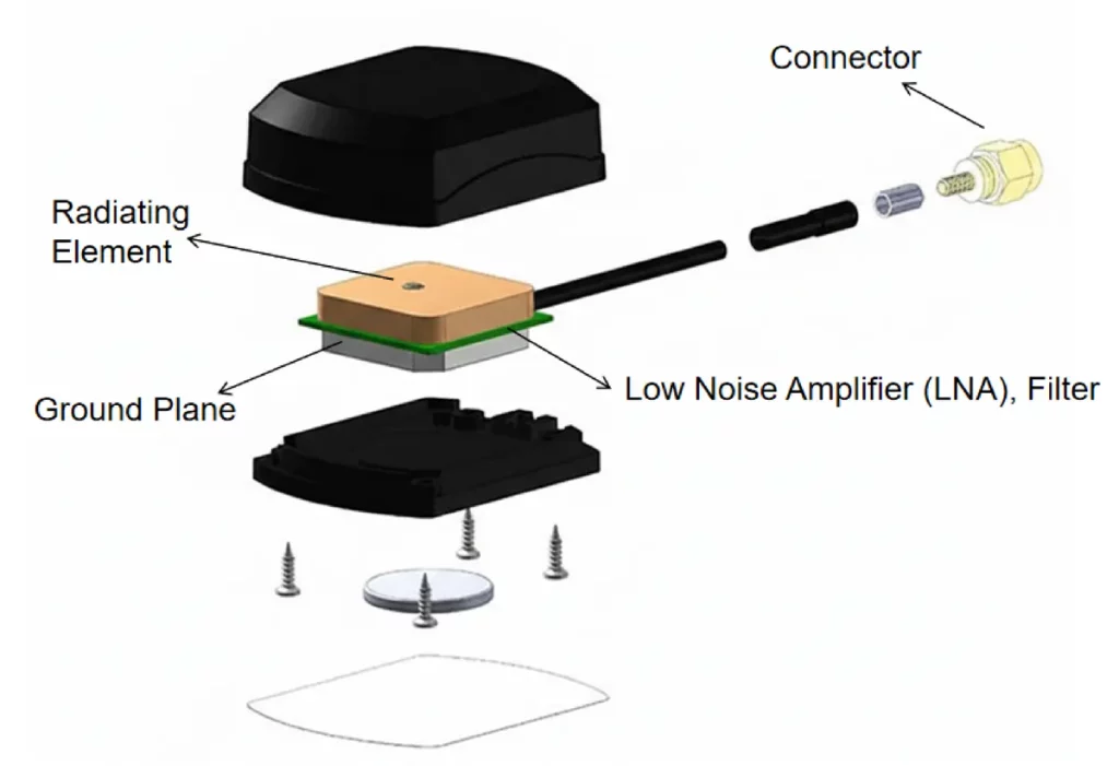
A typical GPS antenna assembly comprises several key components that work in concert to ensure optimal signal reception:
Radiating Element (patch, helix) | These are the core component that physically interacts with the satellite signals. The design of the radiating element determines the antenna’s frequency response, gain pattern, and polarization. |
| Ground Plane | A conductive surface (such as a metal plate) that reflects RF energy and shapes the antenna’s radiation pattern. |
| Low Noise Amplifier (LNA) | Found in active antennas, the LNA boosts weak GPS signals with minimal added noise, improving receiver sensitivity and reducing cable loss impact. |
| Filter | Band-pass filters may be integrated to suppress out-of-band interference while passing the GPS frequencies, enhancing signal quality before amplification. |
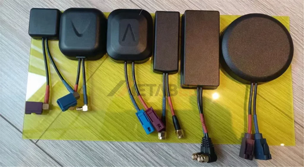
| Connector | Standard RF connectors (SMA, BNC, TNC, etc.) provide a durable interface between the antenna and the receiver or coaxial cable. |
Basic Structure
Types of GPS Antennas
GPS antennas are categorized in several ways depending on power, mounting style, physical design, application, and polarization. Understanding these classifications helps engineers and system integrators select the most suitable antenna for specific positioning accuracy, environmental conditions, and installation constraints.
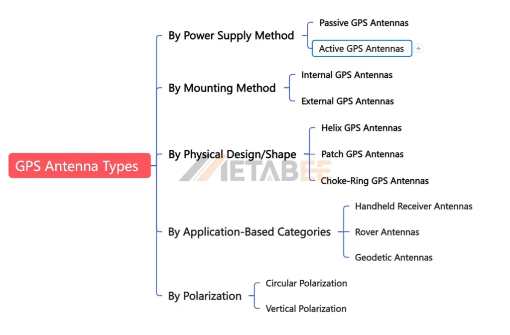
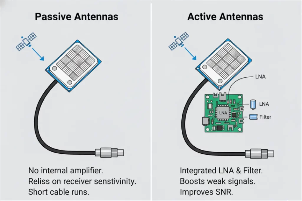
By Power Supply Method: Passive vs. Active Antennas
The most fundamental distinction in GPS antennas is whether they incorporate internal amplification.
- Passive Antennas: Consist only of a radiating element and do not include any internal amplification circuitry. They rely entirely on the receiver’s sensitivity and are typically connected via short coaxial cables to minimize signal loss.
- Active Antennas: These antennas integrate an LNA, and often a filter, directly behind the radiating element. The amplifier boosts weak satellite signals before they travel through the cable, significantly improving signal-to-noise ratio (SNR).
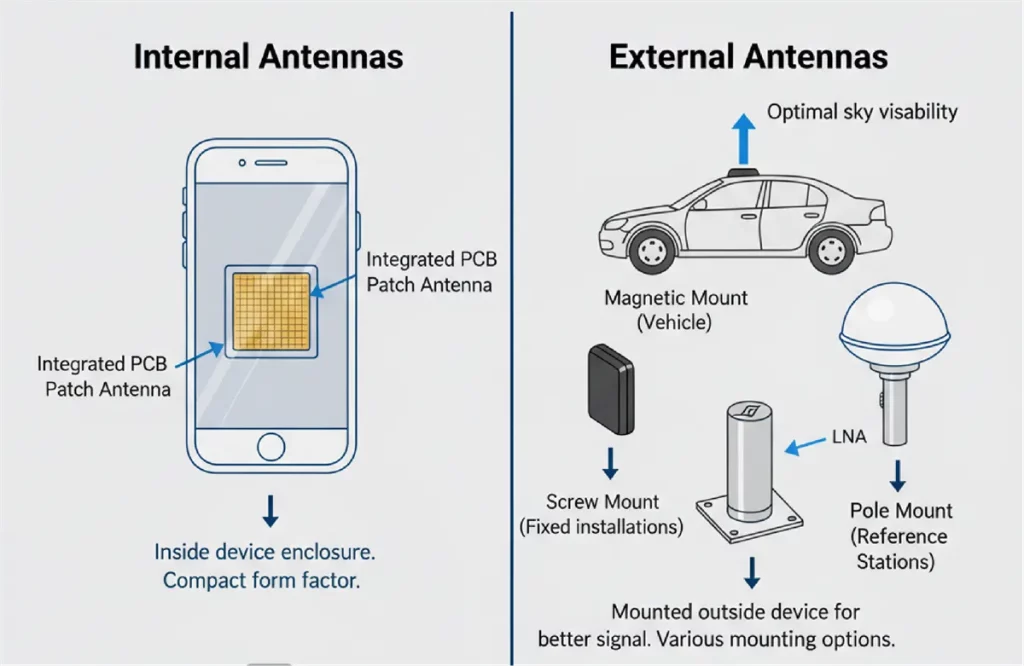
By Mounting Method: Internal vs. External Antennas
- Internal Antennas: They are integrated inside the GPS modules or device enclosures and are usually PCB or small ceramic patch antennas. They offer a sleek form factor and reduced manufacturing complexity.
- External Antennas: Mounted External GPS antennas are mounted outside the device housing, often on vehicles or buildings for optimal sky visibility. Common mounting options include magnetic, screw-mount, adhesive, or pole-mount.
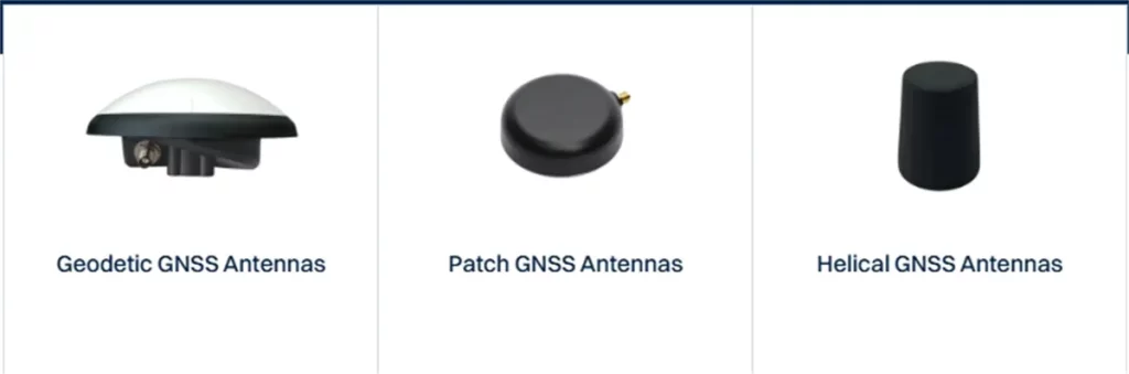
By Physical Design/Shape: Helix VS Patch GPS Antenna VS Choke-Ring Antennas
- Patch GPS Antennas: These are the most widespread due to their compact, flat design. They are cost-effective and provide good performance for single- or dual-band GPS reception in many consumer electronics and industrial applications.
- Helix GPS Antennas: Characterized by their helical coil design, these antennas are often used where a broader radiation pattern or multi-frequency (L1/L2/L5) support is needed. They can be more robust against multi-path effects and are found in some handheld devices and specialized equipment.
- Choke-Ring Antennas: These are high-performance, geodetic-grade antennas featuring concentric “choke” rings around the central radiating element. Their primary purpose is to severely attenuate low-angle signals, thus significantly improving positioning accuracy for demanding applications like surveying and reference stations.
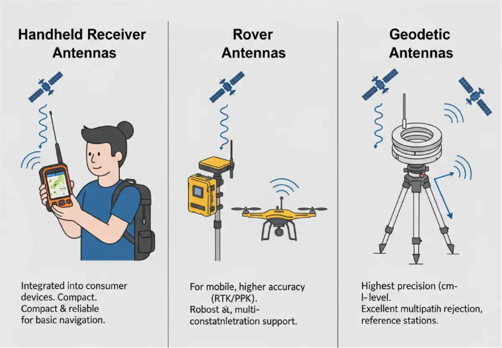
By Application-Based Categories
- Rover Antennas: Designed for mobile applications requiring higher accuracy, such as RTK (Real-Time Kinematic) or PPK (Post-Processed Kinematic) systems in agriculture, construction, or drone mapping. They are robust and often support multiple GNSS constellations.
- Geodetic Antennas: The pinnacle of GPS antenna technology, used in high-precision surveying, scientific research, and permanent reference stations. They feature excellent multipath rejection, superior phase center stability, and multi-frequency, multi-constellation support to achieve centimeter-level accuracy.
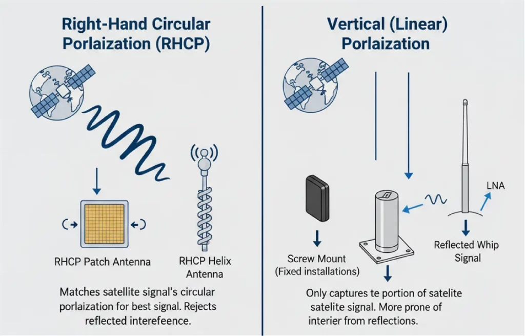
By Polarization
Polarization determines how the antenna “aligns” with the incoming radio wave.
- Right-Hand Circular Polarization (RHCP): Since GPS satellites transmit RHCP signals, a matching RHCP antenna is the industry standard. It provides the best signal efficiency and naturally rejects reflected signals.
- Vertical (Linear) Polarization: While much less common for dedicated GNSS, linear antennas are sometimes used in extremely low-cost or multi-purpose communication modules. But they suffer signal loss and are more prone to interference.
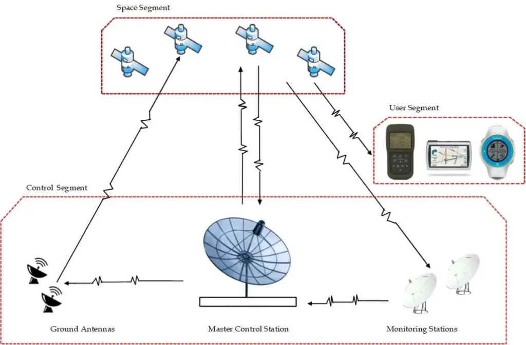
How Does A GPS Antenna Work
A GPS antenna functions as a crucial component in the Global Positioning System, primarily designed to receive weak radio frequency signals transmitted by orbiting GPS satellites.
Here’s a breakdown of how it works:
Signal Reception
The radiating element of the GPS antenna acts as a collector, physically capturing the L-band microwave signals continuously broadcast by the constellation of GPS satellites. These signals are extremely weak by the time they reach Earth’s surface due to the vast distance traveled and atmospheric attenuation.
Signal Amplification and Filtering
Once captured, the raw, weak signals are immediately routed through the internal filter (in active antennas) to remove unwanted radio frequency interference from other sources. Subsequently, the filtered signal is passed to the Low Noise Amplifier (LNA), which boosts its power level significantly without introducing additional noise that could degrade the signal quality.
Data Processing
Once the signals are received and converted, they are sent to a GPS receiver. The receiver then uses the timing and positional data from multiple satellites (at least four are needed for 3D positioning and time) to calculate the user’s precise location, navigation information, and accurate time.
Polarization and Radiation Pattern
RHCP design ensures the antenna efficiently receives signals regardless of satellite orientation, while the radiation pattern (often hemispherical) allows reception across the sky.
Placement and Visibility
Optimal antenna performance relies heavily on its placement. To achieve the best signal acquisition and accuracy, a GPS antenna requires a clear, unobstructed “view” of the sky.
Key Specifications and Performance Parameters
When evaluating GPS antennas, several technical specifications define their performance and suitability for various applications:
Frequency Bands
It refers to the specific GPS signal frequencies the antenna is designed to receive.
- L1 (1575.42 MHz): The primary civilian signal, carrying the Coarse/Acquisition (C/A) code.
- L2 (1227.60 MHz): Used for military P(Y) code and the modern L2C civilian signal, enabling dual-frequency receivers to correct for ionospheric delays and improve accuracy.
- L5 (1176.45 MHz): A newer, more robust “safety-of-life” civilian signal, providing enhanced accuracy and improved interference rejection.
Impedance
Most GPS antennas are a standard impedance of 50 ohms, which matches the input impedance of typical RF receivers and coaxial cables.
Polarization
Right-Hand Circular Polarization (RHCP) is the standard for GPS. The antenna’s ability to efficiently receive RHCP signals is a key performance indicator.
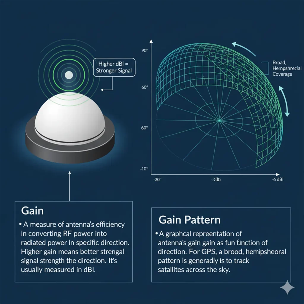
Gain & Gain Pattern
- Gain: A measure of the antenna’s efficiency in converting RF power into radiated power in a specific direction. Higher gain means better signal strength in that direction. It’s usually measured in dBi.
- Gain Pattern: A graphical representation of the antenna’s gain as a function of direction. For GPS, it needs a broad, hemispherical pattern to track satellites across the sky.
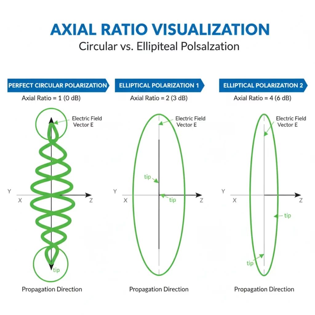
Axial Ratio
For circularly polarized antennas, the axial ratio quantifies how close the polarization is to a perfect circle. An ideal RHCP antenna would have an axial ratio of 1 (or 0 dB). A lower axial ratio (closer to 0 dB) over the antenna’s operational bandwidth indicates better performance and greater immunity to multipath effects.
Noise figure (active antennas)
Specific to active antennas, the noise figure (NF) measures the amount of noise added by the internal LNA. A lower noise figure (typically 1.5 dB or less for high-quality antennas) is crucial, as it preserves the weak satellite signal’s original signal-to-noise ratio, which is vital for precise positioning.
Phase Center Stability
Especially important for high-precision applications (like RTK/PPK), phase center stability refers to how consistently the antenna’s effective electrical center remains stable across different angles of signal arrival and varying frequencies. Instability in the phase center can introduce errors into highly accurate position calculations.
Bandwidth
The range of frequencies over which the antenna maintains acceptable performance. A wider bandwidth is necessary for antennas supporting multiple GPS bands and other GNSS constellations.
Applications of GPS Antennas
GPS antennas are fundamental to countless applications across various industries:
- Surveying and Mapping: Critical for high-precision land surveying, topographic mapping, construction layout, and geographic information systems (GIS) data collection, often utilizing RTK/PPK setups.
- Agriculture: Drives precision farming techniques, including auto-steering for tractors, yield mapping, variable rate application of fertilizers, and drone-based crop monitoring.
- IoT and Asset Tracking: Powers a vast array of Internet of Things devices for tracking logistics, containers, valuable assets, remote monitoring of infrastructure, and smart city applications.

How to Choose GPS Antennas
Selecting the right GPS antenna is critical for optimal system performance. Consider the following factors:
Frequency Bands Support (L1, L2, L5)
Choose an antenna that supports the necessary frequency bands for your application. Single-band L1 antennas are sufficient for basic navigation, while dual- or triple-band antennas (L1/L2, L1/L5, L1/L2/L5) are essential for high-accuracy, multi-constellation GNSS receivers.
Power Consumption (for active antennas)
For battery-powered devices, consider the power consumption of active antennas to ensure it aligns with your device’s energy budget and operational duration.
Size and Form Factor
The physical dimensions and shape of the antenna must fit within the spatial constraints of your product or installation. Consider low-profile, embedded, or external options based on available space.
Mounting Options (magnetic, screw-mount, adhesive)
Ease of installation and secure attachment are important. Common options include magnetic mounts for temporary or flexible installations, screw mounts for permanent, robust fixtures, and adhesive mounts for discreet integration.
Environmental Durability (IP rating)
For outdoor or industrial applications, check the IP rating, which indicates the antenna’s protection level against solid particles (dust) and liquids (water immersion). A higher IP rating (e.g., IP67, IP69K) signifies greater robustness.
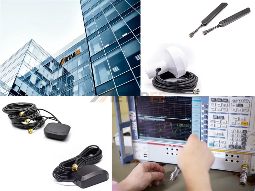
Why Choose Metabee?
Metabee is a professional RF antenna manufacturer and solution provider committed to delivering high-performance, reliable, and application-optimized antenna products for global customers. With a strong focus on GPS, GNSS, RF, and wireless communication technologies, we help customers achieve stable signal performance and long-term operational reliability. Here are several core advantages:
Broad Product Portfolio
We offer a comprehensive range of antenna solutions, including GPS/GNSS, PCB, rubber duck, magnetic-mount, panel-mount, Wi-Fi, and fiberglass antennas.
Strict Quality Control
All antennas undergo rigorous testing, including impedance matching, VSWR, gain, noise figure, and environmental durability checks. We manufacture products under strict quality management systems to ensure stable performance and consistent batch-to-batch reliability.
Global Supply & Professional Service Support
With efficient production capabilities and extensive international logistics expertise, we ensure rapid lead times and dependable global shipping. Our dedicated technical support team offers comprehensive assistance, covering antenna selection, integration guidance, and robust after-sales support.
Cost-Effective Performance
By combining in-house design, manufacturing efficiency, and optimized materials, Metabee provides high-performance antenna solutions at competitive pricing, helping customers reduce total system cost without compromising signal quality.
Engineering-Driven Antenna Design
Our experienced RF engineers develop these antennas using advanced simulation tools and rigorous field testing. We optimize key parameters of every product, such as gain, axial ratio, radiation pattern, and phase center stability, to ensure consistent performance in demanding environments.
Customization and OEM/ODM Support
Metabee supports customized designs for cable lengths, connectors, mounting methods, and multi-band combinations, which is essential for OEM and foreign trade applications that require tailored antenna solutions.
Conclusion
The GPS antenna is a critical RF component that directly influences positioning accuracy, signal stability, and overall GNSS system performance. From basic L1 navigation to multi-band, high-precision applications, the antenna’s design, polarization, gain characteristics, and installation conditions all play a decisive role in signal quality and reliability. Understanding how they work and how to choose the right type can dramatically improve GNSS results under real-world conditions
If you require technical consultation, product selection guidance, or customized GPS antenna solutions, Metabee’s engineering team is available to support your project. Get in touch today for a professional consultation. We’ll analyze your GNSS needs and provide customized solutions designed for your application.
Related Products
- GPS Antenna
- Rubber Duck Antenna
- FPC / PCB antenna
- Wi-Fi Antennas
- Magnetic Antenna
- Fiberglass Antenna
- Panel Mount Antenna
Frequently Asked Questions (FAQ)
Q1: What is the main difference between passive and active GPS antennas?
A: Passive antennas do not have an internal amplifier and rely on the receiver for signal boosting, suitable for short cable runs. Active antennas have a Low Noise Amplifier (LNA) and filter with power and can provide amplified, cleaner signals, ideal for long cables and noisy environments.
Q2: Which frequency bands does a GPS antenna support?
A: A GPS antenna typically supports the following frequency bands:
- L1 (1575.42 MHz): This is the primary civilian signal, carrying the Coarse/Acquisition (C/A) code.
- L2 (1227.60 MHz): Used for the military P(Y) code and the modern L2C civilian signal. Antennas supporting L2 enable dual-frequency receivers to correct for ionospheric delays, which improves accuracy.
- L5 (1176.45 MHz): This is a newer, more robust “safety-of-life” civilian signal designed for enhanced accuracy and improved interference rejection.
Q3: Why is circular polarization important for GPS antennas?
A: GPS satellites transmit Right-Hand Circularly Polarized (RHCP) signals. Using an RHCP antenna maximizes the reception efficiency of these signals and significantly reduces the impact of multi-path interference, which occurs when signals reflect off surfaces.
Q4: Can a GPS antenna support multiple GNSS constellations?
A: Yes. Many modern GPS antennas support multi-GNSS reception, including GPS, GLONASS, Galileo, and Bei-Dou. Multi-band designs improve satellite visibility and positioning performance in challenging environments.
Q5: How far can I run cable from the GPS antenna to the receiver?
A: The maximum cable length depends on antenna gain, cable quality, and total signal loss. High-gain antennas and low-loss coax can support longer runs. But total attenuation must remain within acceptable limits for the receiver to maintain lock.