


Have you ever stumbled across an old, D-shaped cable in a drawer, perhaps while cleaning out an old gaming PC or sorting through vintage audio equipment? With its distinctive shield and two rows of pins, you were likely staring at a DB15 connector, a member of the D-Sub connector family.
Throughout this comprehensive guide, we will clear up the technical confusion. This article focuses entirely on the two-row DB15, uncovering its crucial roles in early PC history and modern specialized equipment. We will delve into the distinct historical and specialized modern applications of the two-row DB15, offering crucial clarity for anyone dealing with legacy hardware or specialized industrial systems
What is a DB15 Connector?
DB15 Connector Defination
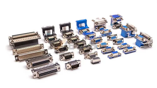
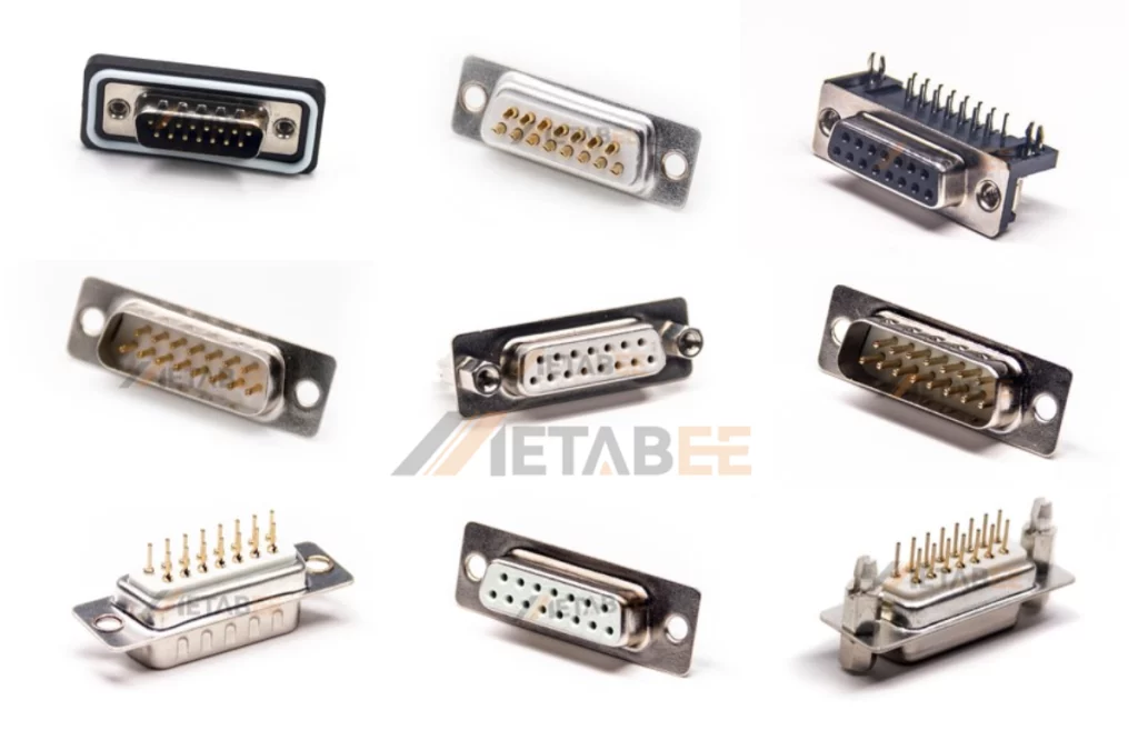
The DB15 connector (technically DA15) is a member of the D-Subminiature family. It features a D-shaped metal shell (A shell size) and 15 pins arranged in two rows (8 on top, 7 on the bottom) with a standard 2.77 mm pitch. Originally designed for robust analog signal transmission, it served as the standard interface for PC Game Ports, MIDI instruments, and early Macintosh video displays before the advent of USB.
Related Post: What is a DB25 Connector? A Deep Dive into this D-Sub Connector
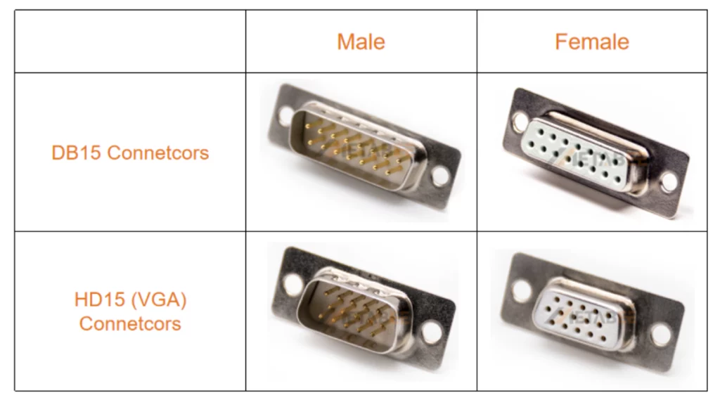
The Confusion Factor: DB15 vs. HD15 (VGA)
To clear up the most common hardware confusion: we are focusing on the two-row DB15 connector, or standard-density 15-pin D-sub connector.
The VGA connector is fundamentally different from the DB15 connector, which is technically called the HD15 (High-Density) connector. The HD15 connectors use three rows of pins (5 pins per row) and feature a tighter 2.29 mm pitch. And their E-size shell are smaller than the DB15 connector’s A-size shell.
Related Post: DB15 vs VGA: The Surprising Differences Between DB15 and VGA
Primary Application: The Game Port and Joysticks
For millions of early PC users, the DB15 connectors were synonymous with entertainment, serving as the Game Port.
The Golden Age of PC Gaming
From the mid-1980s through the late 1990s, the DB15 connectors were the standard interface for connecting joysticks, flight yokes, and early gamepads to a personal computer. It was typically integrated onto dedicated sound cards, such as the Creative Sound Blaster series. These cards provided the dedicated circuitry needed to handle the controller inputs. Without this port, gaming was limited to the keyboard. This connector was the gateway to titles like Wing Commander, Descent, and countless other classic simulators and arcade games.
Game Port Signal Breakdown
The Game Port utilized the DB15 connectors to support up to four analog axes and four digital buttons. The key to DB15 connectors’ operation was their analog input mechanism, which was surprisingly simple:
- Analog Axes (X and Y): Pins were connected to the variable resistors inside the joystick. The PC measured the resistance changes as the joystick was moved.
- Conversion: The PC’s Game Port chip would charge a small capacitor through the joystick’s resistor. The time it took for the capacitor to charge to a certain voltage level determined the joystick’s position. This time-to-voltage conversion was inherently slow, limiting the precision and speed of the controller. But it was perfectly adequate for the era.
- Digital Buttons: Four dedicated pins allowed for simple, digital on/off signaling for fire buttons. These pins typically include Pin 4 (Button 1), Pin 12 (Button 2), Pin 7 (Button 3), and Pin 15 (Button 4).
Game Port (DB15) Pin Assignments
This table details the standard pin assignments for the two-row DB15 connector when used as a PC Game Port (found typically on sound cards). The pinout is shown from the perspective of the female connector (the port on the computer).
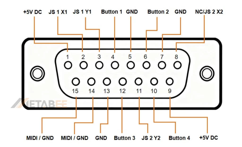
| Pin No. | Signal Name | Function Description |
| 1 | +5V DC | 5 Volt DC Power Supply (Used for joysticks/controllers). |
| 2 | JS 1 X1 | Joystick 1 X-axis (Analog Input for horizontal movement). |
| 3 | JS 1 Y1 | Joystick 1 Y-axis (Analog Input for vertical movement). |
| 4 | Button 1 | Joystick 1 Button 1 (Digital Input). |
| 5 | GND | Ground / Common Ground (Signal Reference). |
| 6 | Button 2 | Joystick 1 Button 2 (Digital Input). |
| 7 | GND | Ground / Common Ground. |
| 8 | JS 2 X2 | Joystick 2 X-axis (Analog Input). |
| 9 | +5V DC | 5 Volt DC Power Supply. |
| 10 | Button 4 | Joystick 2 Button 2 (Digital Input). |
| 11 | JS 2 Y2 | Joystick 2 Y-axis (Analog Input). |
| 12 | Button 3 | Joystick 2 Button 1 (Digital Input). |
| 13 | GND | Ground / Common Ground. |
| 14 | MIDI TX / GND | MIDI Transmit (Used in MIDI mode) or Ground (in Game Port mode). |
| 15 | MIDI RX / GND | MIDI Receive (Used in MIDI mode) or Ground (in Game Port mode). |
The MIDI Connection
Beyond gaming, the Game Port offered a fantastic dual purpose: it often doubled as a MIDI (Musical Instrument Digital Interface) port. By utilizing the same DB15 connector and a specialized breakout cable, the port could transmit and receive MIDI data. This was invaluable for early PC-based music production. How? It connected synthesizers, keyboards, and drum machines to the computer. As a result, the DB15 became a critical component for both gamers and musicians.
Second Primary Application: Ethernet Networking
While the Game Port dominated the consumer market, the DB15’s professional application was equally important: early Ethernet networking.
The AUI Standard (Attachment Unit Interface)
In the world of corporate and academic networks, the DB15 was the standard connector for AUI (Attachment Unit Interface). The AUI served to link the computer’s internal Network Interface Card (NIC) with an external Medium Attachment Unit (MAU), also called a transceiver. The MAU handled the actual signal transmission onto the physical network cable.
10BASE5 (Thicknet) Infrastructure
The AUI connector was most famously used with 10BASE5 Ethernet, the original thick coaxial network standard (often nicknamed the “Yellow Cable”). The AUI cable would run from the NIC to the MAU. The MAU would then be attached to the thick coaxial trunk cable using a “vampire tap,” which pierced the cable’s core conductor. The DB15 offered the necessary number of pins to reliably transfer all the digital and control signals between the NIC and the external transceiver.
AUI Pin Assignments for Networking
The AUI standard meticulously assigned pins to manage complex networking tasks, unlike the Game Port, which carried only simple analog and digital signals. Key functions and their common pin assignments (using the two-row DB15 connector) included:
- Transmit Data (TD): Sending data from the computer. Uses a differential pair: TD+ (Pin 3) and TD- (Pin 10).
- Receive Data (RD): Receiving data from the network. Uses a differential pair: RD+ (Pin 5) and RD- (Pin 13).
- Collision Detect (CD): A critical line used by the MAU to signal to the NIC that two stations attempted to transmit data simultaneously, requiring a retry. Uses a differential pair: CD+ (Pin 2) and CD- (Pin 9).
- Voltage: Power supply for the MAU, typically using Pin 6 and Pin 12.
- Grounding: The shell (Pin 1) and multiple pins were reserved for signal and power grounding to ensure reliable data transfer over long, noisy network segments.
AUI (DB15) Pin Assignments
The table below details the standard pin assignments for the two-row DB15 connector when used as the Attachment Unit Interface (AUI) for Ethernet networking.
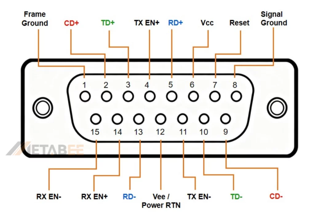
| Pin No. | Signal Name | Function Description |
| 1 | Frame Ground | Outer shell/chassis ground for shielding. |
| 2 | CD+ | Collision Detect Signal Plus (Positive leg of CD differential pair). |
| 3 | TD+ | Transmit Data Signal Plus (Positive leg of TD differential pair). |
| 4 | TX EN+ | Transmit Enable Signal Plus (Positive leg of TX_EN differential pair). |
| 5 | RD+ | Receive Data Signal Plus (Positive leg of RD differential pair). |
| 6 | Vcc | Power Supply (Typically +12V DC for the MAU). |
| 7 | Reset | Reset/Control Signal (or No Connection). |
| 8 | Signal Ground | Signal Reference Ground. |
| 9 | CD- | Collision Detect Signal Minus (Negative leg of CD differential pair). |
| 10 | TD- | Transmit Data Signal Minus (Negative leg of TD differential pair). |
| 11 | TX EN- | Transmit Enable Signal Minus (Negative leg of TX_EN differential pair). |
| 12 | Vee / Power RTN | Power Return / Ground. |
| 13 | RD- | Receive Data Signal Minus (Negative leg of RD differential pair). |
| 14 | RX EN+ | Receive Enable Signal Plus (Positive leg of RX_EN differential pair). |
| 15 | RX EN- | Receive Enable Signal Minus (Negative leg of RX_EN differential pair). |
Other Legacy Networking Uses
In addition to its primary functions, the DB15 connector also served in early networking hardware like Token Ring adapters. In fact, before the RJ-45 connector took over, the DB15 connectors had firmly established themselves as a versatile and widely adopted workhorse for data connections.
Specialized, Industrial, and Custom Uses
The DB15 connectors’ rugged shell and defined pin structure made it a preferred choice for applications far outside the home PC.
Data Acquisition and Control Systems
The DB15 connector’s robust physical design was ideal for reliable data transfer in industrial environments where vibration and electrical noise are common. DB15 ports were frequently used as I/O (Input/Output) interfaces for PLC (Programmable Logic Controller) programming units. They provided a trustworthy, latching connection ideal for transferring configuration and diagnostic data. This made them a common sight in manufacturing and automation environments.
RS-422 and RS-485 Serial Communications
In professional video, stage lighting, and large-scale industrial control, the DB15 connector was adopted for specialized serial communications like RS-422 and RS-485. These protocols use differential signaling, which makes them highly immune to electrical noise. This allows for reliable data transmission over much greater distances than standard RS-232 serial ports. This made the DB15 the go-to connector for certain video editing suites, point-of-sale systems, and remote telemetry applications.
Test and Measurement Equipment
Many specialized electronic tools, like oscilloscopes and spectrum analyzers, relied on the DB15 for external sensor I/O. It provided a compact and sturdy multi-pin connection, which was ideal for handling their proprietary signals.
DB15 in the Modern Era: Is It Still Used?
So, is the DB15 a connector of the past? Largely, yes. In the consumer world, superior digital standards like USB and HDMI have decisively superseded this legacy interface.
However, it is not entirely dead. Its relevance persists in several key areas:
- Maintaining Legacy Systems: Many businesses and institutions still rely on old but functional equipment that requires DB15 connections.
- Industrial Applications: In factories and manufacturing, the cost of replacing entire systems is prohibitive, so DB15-based control systems remain in operation.
- The Adapter Market: There remains a consistent need to connect old VGA monitors to modern laptops and PCs. As a result, a thriving market for active adapters (e.g., VGA to HDMI or USB-C) has emerged. Thus, the DB15 connector maintains its indirect relevance today.
Conclusion
This comprehensive guide explores the primary uses of the two-row DB15 connector. We clarified its primary roles: serving as the classic PC Game Port for joysticks, doubling as a MIDI interface for musicians, and functioning as the AUI for early Ethernet networks. Beyond consumer electronics, we also covered its specialized applications in industrial control and data acquisition systems. While now largely a legacy interface, its impact was profound. We hope this guide has given you a comprehensive understanding of this rugged workhorse’s significant role in the history of computing and technology.
Related Products
- DB15 Connectors
- HD15/VGA Connectors
- D-Sub Connectors
- Combo D-Sub Connectors
- Stacked D-sub Connectors
- Waterproof D-Sub Connectors
FAQ Section
Q: Is a DB15 the same as a VGA connector?
A: No. The true DB15 has two rows of pins and was used for gaming and networking. The VGA connector is an HD15 (High-Density), which has three rows and is solely for video.
Q: What was the primary purpose of the DB15 Game Port?
A: It provided an interface for connecting up to two analog joysticks or four digital buttons to a PC, typically found on sound cards.
Q: Can I convert a DB15 Game Port to USB?
A: Yes, but you need an active adapter. The original Game Port sends an analog signal based on resistance. Therefore, you need a converter with internal electronics to translate that data into a digital USB signal. A simple wire-based passive adapter will not work.
Q: Is DB15 the same as RS232?
A: No. RS232 refers to the serial communication standard, typically using a 9-pin (DB9) or 25-pin (DB25) connector. With its unique pin arrangement, the DB15 served I/O (Game Port) and video (VGA). The DB15 connector did not serve standard RS-232 serial communication.
Q: What common PC components featured a DB15 port?
A: Historically, it was most often found on dedicated sound cards (for the Game Port/MIDI) and older Ethernet network interface cards (for AUI).
Q: What modern interface replaced the DB15 Game Port?
A: USB (Universal Serial Bus) completely replaced the DB15 for game controllers, offering digital signaling, higher speed, and ease of use.