


In the vast world of computer hardware, a sea of cables and connectors can often lead to confusion. The most frequently mixed-up are the DB15 and VGA connectors. While they may seem similar at first glance, their differences are crucial for achieving the right connection.
This guide cuts through the confusion to break down the key differences between DB15 and VGA connectors, from their pin configurations to real-world applications. By the end, you’ll have the clarity to select the right connector for your project, avoid common mistakes, and ensure seamless performance across your systems.
Introduction of DB15 and VGA Connectors
What is a DB15 Connector?
The DB15 connectors is a member of the D-Subminiature (D-Sub) family. The standard DB15 connector uses a naming convention that specifies the shell size and the number of pins. The DB15 is technically a DA15. “D” is the D-Subminiature; the “A” prefix simply means it has an A-size shell, and the number “15” denotes it has 15 pins.
Related Post: What is a D-Sub Connector?
Physical Characteristics
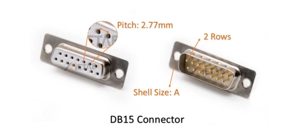
The features of the standard DB15 connectors:
- It features a D-shaped metal shell in the A size.
- 2 rows of pins (one with 8 pins, the other with 7 pins) with a pin pitch of 2.77mm.
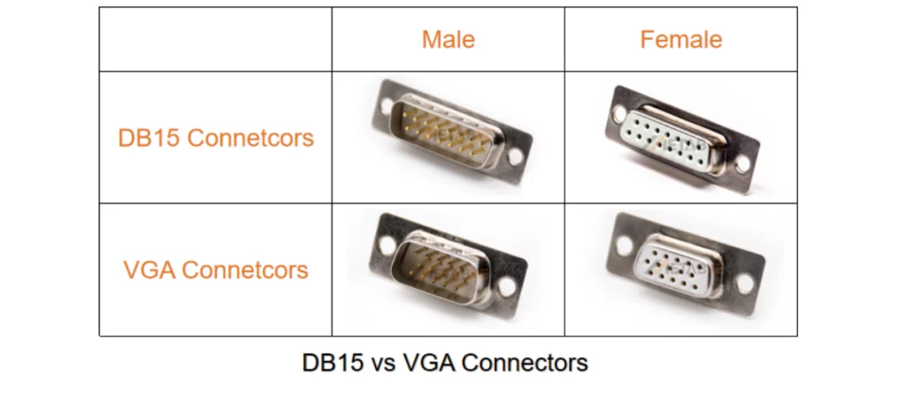
- Typically found in male (plug) and female (socket) versions.
Common Applications of the DB15 Connector
Due to its age and design, the standard DB15 connector is mostly a legacy component today. Its common uses include:
- Legacy Gaming Ports: It was widely used for connecting joysticks and gamepads on older personal computers.
- Older Networking Applications: It served as an Attachment Unit Interface (AUI) port for connecting Ethernet transceivers on older networking equipment.
- Industrial and Scientific Equipment: It is still found on some specialized and proprietary industrial control systems.
What is a VGA Connector?
The term “VGA connector” is commonly used to refer to the HD15 connectors, a kind of high-density D-Sub connectors. IBM introduced it in 1987 with its Video Graphics Array (VGA) display standard. While everyone calls it “VGA,” its technical name is actually DE15. The “E” denotes a smaller E-size shell, and it has 15 pins. It’s also widely known as an HD15 (High-Density) connector.
Physical Characteristics
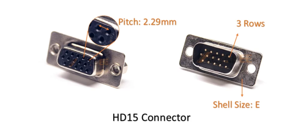
The features of the VGA (HD15) connectors:
- A D-shaped metal shell (E-size shell) that is physically smaller than a DB15’s shell.
- 3 rows of pins (with 5 pins in each row) and a pin pitch of 2.29mm.
- It is almost exclusively used for analog video signals (Red, Green, Blue, Horizontal Sync, Vertical Sync).
Primary Applications
The VGA connector’s primary application has always been analog video transmission. Its common uses are:
- Computer-to-Monitor Connection: The industry-standard way to connect a computer to a monitor or projector for decades.
- Video Cards: The standard output port on most graphics cards before the rise of digital interfaces.
- Video Display Systems: It is still widely used in many professional, educational, and industrial display systems.
DB15 vs. VGA (HD15): A Head-to-Head Comparison
Pin Configuration Breakdown
The most significant difference between a DB15 and a VGA connector lies not just in the number of rows, but in what each pin is engineered to do. The physical layout, known as the pinout, dictates the function of the connector.
To visualize this difference, let’s look at the pin numbering for both connector types. Notice how the pins are counted sequentially from right to left across the rows.
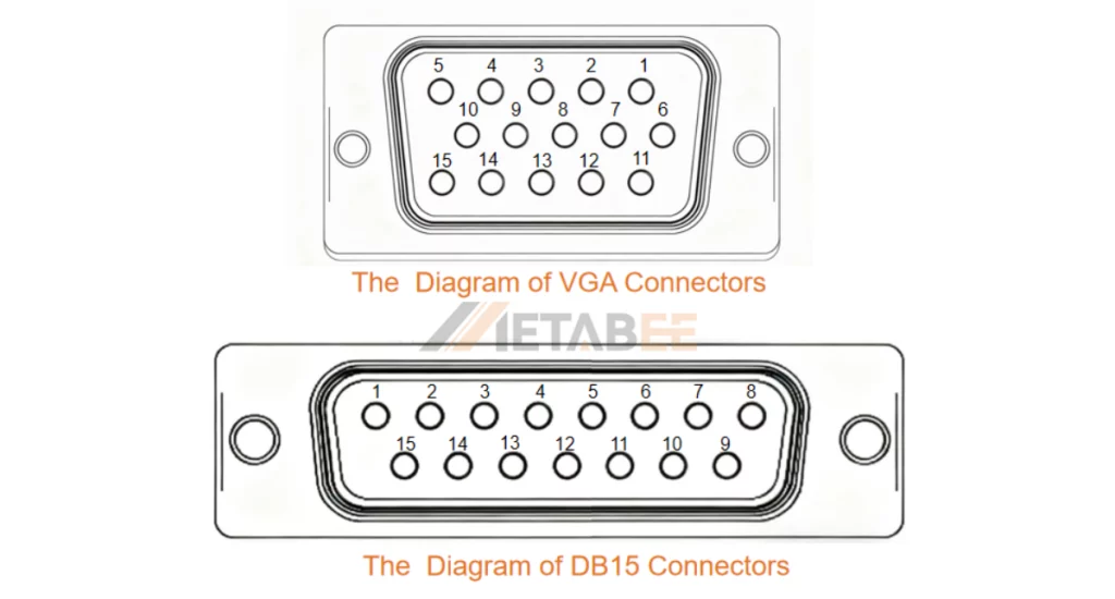
As the diagrams illustrate, the pin arrangement refers to the specific function assigned to each of the 15 pins. The tables below show how their internal wiring is engineered for completely different purposes.
| Pin Number | DB15 Typical Function (RS-232/Industrial) | VGA Function (Analog Video) |
|---|---|---|
| 1 | Data Transmit (TXD) | Red Video (R) |
| 2 | Data Receive (RXD) | Green Video (G) |
| 3 | Ground (GND) | Blue Video (B) |
| 4 | Data Terminal Ready (DTR) | Monitor ID Bit 1 |
| 5 | Ground (GND) | Monitor ID Bit 2 |
| 6 | Data Set Ready (DSR) | Ground (GND) |
| 7 | Ground (GND) | Ground (GND) |
| 8 | Request to Send (RTS) | Ground (GND) |
| 9 | Clear to Send (CTS) | Key (No Pin) |
| 10 | Ground (GND) | Ground (GND) |
| 11 | Ring Indicator (RI) | Horizontal Sync (HSYNC) |
| 12 | Secondary Data Transmit (Optional) | Monitor ID Bit 3 |
| 13 | Secondary Data Receive (Optional) | Vertical Sync (VSYNC) |
| 14 | Secondary Clear to Send (Optional) | Monitor ID Bit 4 |
| 15 | Secondary Request to Send (Optional) | Ground (GND) |
Pin Pitch and Density
This refers to the distance from the center of one pin to the center of an adjacent pin.
- DB15 (Standard Density): The traditional DB15 connector has a pin pitch (the center-to-center distance between rows of pins) of 2.77mm. This was the standard for the original D-Sub family.
- VGA/HD15 (High Density): The VGA connector is more correctly an HD15, where the “HD” stands for High Density. To fit 15 pins into a smaller shell, the pin pitch was reduced to 2.29mm.
Shell Size
The shell size is the final piece of the physical puzzle, and it’s directly linked to the pin pitch.
- DB15 (A-Size): The standard DB15 connector uses an A-size shell. This shell was originally designed for connectors with up to 15 pins at the standard 2.77mm pitch.
- VGA/HD15 (E-Size): The VGA connector (HD15) uses a smaller E-size shell. The “high-density” pin layout (2.29mm pitch) allowed engineers to fit 15 pins into this more compact E-size shell.
Specifications
The table below outlines the typical specifications you would find on a component datasheet.
| Connector Type | DB15 Connector | VGA(HD15) Connetcor |
|---|---|---|
| Number of Rows | 2 rows | 3 rows |
| Pitch | 2.77mm | 2.29mm |
| Shell Size | A | E |
| Number of Contacts | 15 | |
| Mounting Type | Cable Mount, PCB Mount | |
| Voltage Rating | 250V AC / 300V DC | |
| Current Rating | 5A | |
| Contact Resistance | < 20 mΩ | |
| Insulation Resistance | > 1000 MΩ | |
| Shell Material | Steel or Zinc Alloy | |
| Shell Plating | Nickel Plating | |
| Contact Material | Brass or Phosphor Bronze | |
| Contact Plating | Gold Plating or Tin Plating | |
| Insulator Material | PBT or Glass-Filled Thermoplastic (UL94V-0) | |
| Operating Temperature | -55°C to +125°C | |
Why the Confusion Exists and Why It Matters
The confusion stems from simple visual similarity and colloquial language. People saw a 15-pin D-Sub connector and called it a “DB15,” and the name stuck—even for the physically different VGA connector.
Why does this matter?
- Physical Incompatibility: You cannot plug a two-row DB15 cable into a three-row VGA port, and vice-versa. Forcing it will bend and break the pins.
- Electrical Incompatibility: Even if you could force a connection, the devices won’t work together. The signals they use are completely different. For example, plugging a network cable into a VGA port will not send a video signal. More importantly, it might create a short circuit and damage the equipment.
How to Choose Between DB15 and VGA
Choosing the correct cable might seem complicated, but it’s actually a straightforward process of matching the connector to the device’s function. Here’s a simple guide to ensure you select the right one every time.
Identify Your Device’s Purpose
The first and most important step is to understand what you are trying to connect:
- For Video (Monitors, Projectors, PCs): You will need a VGA connector when connecting a device for video display, such as a computer to a monitor or a laptop to a projector. VGA ports are designed specifically for transmitting analog video signals.
- For Legacy Peripherals (Joysticks, MIDI, Old Networks): If you are working with older or specialized equipment, you might need a DB15 connector. Its most common historical use was for the game port on sound cards and motherboards for connecting joysticks. It was also used for AUI network connections or older MIDI devices.
Checking Your Device
The quickest and most reliable way to differentiate between a DB15 and a VGA connector is to count the rows of pins.
- 2 Rows of Pins: This is a DB15 connector. The pins are more spread out in a two-row formation (one row of 8 pins, one row of 7).
- 3 Rows of Pins: This is a VGA / HD15 / DE15 connector. The high-density, three-row layout is the universal standard for analog video.
Conclusion
This article has clarified the key differences between the standard DB15 and the VGA (HD15) connector. While they look similar, the DB15 has two rows of pins and was used for legacy gaming and data, whereas the VGA connector has three rows and is dedicated to analog video.
Understanding this distinction prevents the frustration of buying incompatible cables and damaging your devices. The simplest way to tell them apart is to count the pin rows. We are confident that after reading this guide, you can now confidently identify and choose the correct connector for your needs.
Related Products
- DB15 Connectors
- HD15/VGA Connectors
- D-Sub Connectors
- Combo D-Sub Connectors
- Stacked D-sub Connectors
- Waterproof D-Sub Connectors
Frequently Asked Questions (FAQs)
Q1: Is a VGA connector the same as a DB15?
A: No. While people often colloquially call it a DB15, the VGA connector technically qualifies as a high-density D-Sub (HD15 or DE15). It arranges its 15 pins in three rows. In contrast, a standard DB15 uses two rows for its 15 pins and typically serves older, non-video applications.
Q2: Can I use a DB15 cable for my monitor?
A: No. A standard DB15 cable will not physically fit a VGA port on a monitor because the two-row pin arrangement is incompatible with the three-row VGA port. You need a VGA (HD15) cable.
Q3: Why is a VGA connector sometimes called an HD15 connector?
A: “HD” stands for “High-Density”. It signifies that the 15 pins are in a more compact, three-row arrangement compared to the standard, larger two-row DB15. It is another common name for the VGA connector.
Q4: Are DB15 connectors still used today?
A: Of course. While largely replaced by USB for peripherals, DB15 connectors can still be found on some legacy systems and specialized industrial equipment.
Q5: What are the main advantages of a high-density connector like the HD15?
A: The primary advantage is a smaller physical footprint. This allowed manufacturers to fit a full 15-pin connector onto compact devices like computer expansion cards without taking up excessive space on the back panel.
Pingback: What is a DB15 Connector Used For? - MetabeeAI