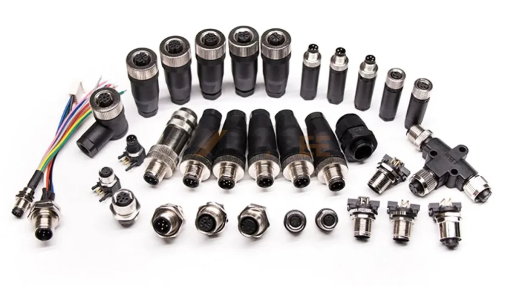
M12 connectors are essential parts of industrial automation systems. These circular connectors provide a durable and reliable solution for making electrical connections. They are small, versatile, and can withstand dirt, moisture, and vibrations. As a result, they are perfect for factories, power plants, and other industrial environments. M12 connectors are available in various coding schemes, each with a specific pin configuration tailored for different applications. This guide will cover everything you need about the M12 connector pinout, color code, and wiring diagram. Furthermore, I will provide a downloadable PDF guide to help you create secure and error-free connections.
Understanding the pinouts, color codes, and wiring diagrams of M12 connectors can help you make reliable connections in your industrial automation systems. This tutorial will help you navigate the world of M12 connectors and ensure they perform optimally in your applications.
- What are M12 connectors?
- M12 Connector Coding: The Language of Industrial Connections
- What Are the Pinout, Color Codes, and Wiring Diagrams of M12 Connectors?
- Why Are the Pinout, Color Codes, and Wiring Diagrams So Important?
- M12 Connector Pinout, Color Codes, and Wiring Diagrams
- M12 Connector Pinouts, Color Codes, and Wiring Diagrams for Applications
- Important Considerations When Working with M12 Connectors
- Conclusion
- Related Products
- Download this Free Guide
What are M12 connectors?
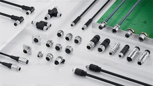
M12 connectors are metric circular connectors that use a 12mm locking thread interface. They are the hidden heroes of industrial automation, quietly ensuring the consistent flow of data and power throughout complicated systems. They are made of high-quality materials such as nickel-plated brass or stainless steel, which provides outstanding durability and corrosion resistance. The strong shell protects the internal components from shock, vibration, and severe temperatures, which can be troublesome in industrial environments.
Locking Mechanisms
M12 connectors feature a threaded coupling that needs to be screwed together for a secure connection. This design provides the greatest strength and vibration resistance.
Making the Connection
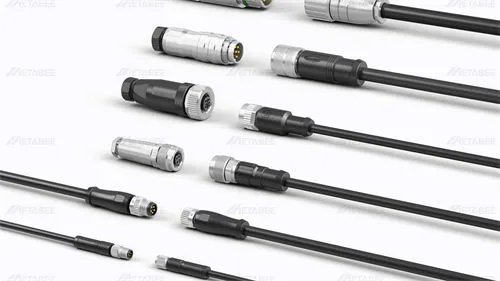
M12 connectors come in two genders: male and female. M12 male connectors have protruding pins, while M12 female connectors have corresponding sockets. When connected, the pins fit tightly into the sockets, establishing an electrical connection. The coding system dictates the pin layout and ensures proper functionality.
Key Distinction: Coding and Functionality
One of the distinguishing features of M12 connectors is their coding system. Unlike general plug-and-play connectors, M12 connectors come in various coding types, represented by letters like A, B, C, D, X, etc. Each coding scheme has a distinct pinout configuration that determines the function of each pin in the connector. For example, a M12 4-pin A-coded connector is designed for sensor signals, while a M12 4-pin D-coded connector is used for industrial Ethernet. This coding system prevents unintentional mismatches and ensures the proper flow of data or power within your system.
Related Post:
What is an M12 Connector? A Complete Overview
M12 Connector Coding: The Language of Industrial Connections
Imagine a factory floor bustling with activity. Machines whir, sensors collect data, and signals travel seamlessly between devices. M12 connectors are essential for keeping things running smoothly. But how do these connectors know what kind of data to carry or how much power to deliver? The answer lies in their unique coding system.
M12 Codes
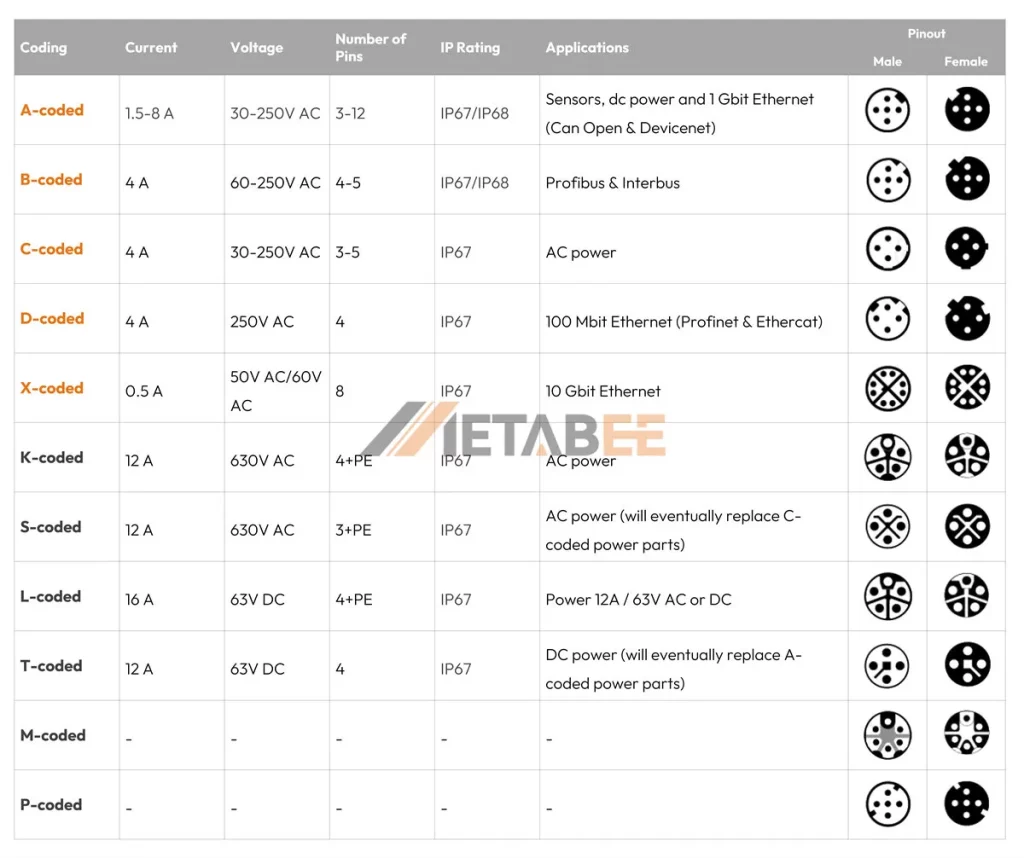
M12 connector coding serves as a language, dictating the functionality of each pin within the connector. Different coding types, represented by letters (A, B, C, D, X, etc.), have different pinout configurations that cater to various applications. Here are some popular M12 coding schemes and their applications:
- A-coded for sensors, DC power, and 1 Gbit Ethernet (Can Open & DeviceNet)
- B-coded for Profibus & Interbus
- C-coded for AC power
- D-coded for 100 Mbit Ethernet (Profinet & Ethercat)
- X-coded for 10 Gbit Ethernet
- S-coded for AC power (will eventually replace C-coded power parts)
- T-coded for DC power (will eventually replace A-coded power parts)
- L-coded for power 12A / 63V AC or DC
I published a blog post about M12 connector types. You can learn more information about M12 connector coding in this post.
What Are the Pinout, Color Codes, and Wiring Diagrams of M12 Connectors?
M12 connectors are reliable and adaptable for industrial applications, but their true power lies in their versatility. Understanding the pinouts, color codes, and wiring diagrams relevant to each M12 coding type allows you to unlock the potential of these connectors. In addition, you’ll ensure error-free connections within your system.
Pinout
Imagine a roadmap for an electrical connection. That is exactly what an M12 connector pinout looks like. It describes the pin configuration of an M12 connector, indicating which pins are pins 1 and 2 and their positions. Pinout configurations for M12 connectors vary depending on the coding type. Before attaching any device to an M12 connector, check the pinout to ensure it is compatible with the device.
Color Code
M12 connector color codes indicate the color of the wires connected to the pins. Each pin in the connector is assigned a color, and the matching wire on the cable must match that color. This visual cue reduces the possibility of errors during installation, particularly when working with several M12 connectors.
Color codes are mainly used for M12 cables and bulkhead connectors. For some industries and applications, the color code has default rules. For example, for an M12 A-coded 4-pin connector, pin 1 is connected to the brown wire, pin 3 to the blue wire, and pin 4 to the black wire.
Wiring Diagram
A wiring diagram is a blueprint for M12 cables, splitters, and M12 to RJ45 cables. It uses the pinout information from each connector to visually represent how the associated pins should be wired together. Consider it a step-by-step guide to ensure data or power flows properly across connected devices.
Why Are the Pinout, Color Codes, and Wiring Diagrams So Important?
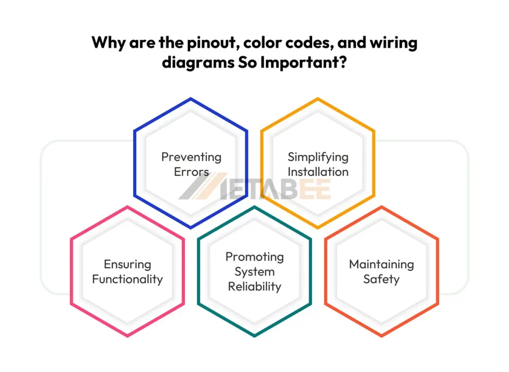
M12 connectors are so important for industrial automation. They ensure the smooth flow of data and power in complicated systems. However, their functionality is dependent on making the correct connections. This is where pinouts, color codes, and wiring diagrams come in.
Preventing Errors
Miswiring an M12 connector can lead to disastrous results. Incorrect pin arrangement can cause device damage, disrupt system communication, and possibly constitute a safety risk. Following the designated pinout and color code ensures each wire connects to the correct pin, avoiding costly mistakes.
Simplifying Installation
Consider working on a complex system that uses numerous M12 connectors. Pinouts and wiring diagrams serve as a road map, clearly illustrating how each connector should be wired. This saves you time and effort during installation, especially when working with various M12 coding types.
Ensuring Functionality
Each M12 coding type has a specific purpose. A-coded connectors are created for low-power applications, whereas D-coded connectors are suitable for Ethernet connections. Following the pinout and wiring diagram related to the coding type ensures that data or power flows as expected.
Promoting System Reliability
Reliable connections are the backbone of any robust industrial automation system. Pinouts, color codes, and wiring diagrams let you make secure and error-free connections. This reduces downtime caused by incorrect connections while ensuring your system runs smoothly.
Maintaining Safety
In industrial settings, safety is important. Improper connections with M12 connectors can lead to potential overheating or sparking, generating security risks. Following the specified pinout and wiring diagram prevents such scenarios and supports a safe working environment.
M12 Connector Pinout, Color Codes, and Wiring Diagrams
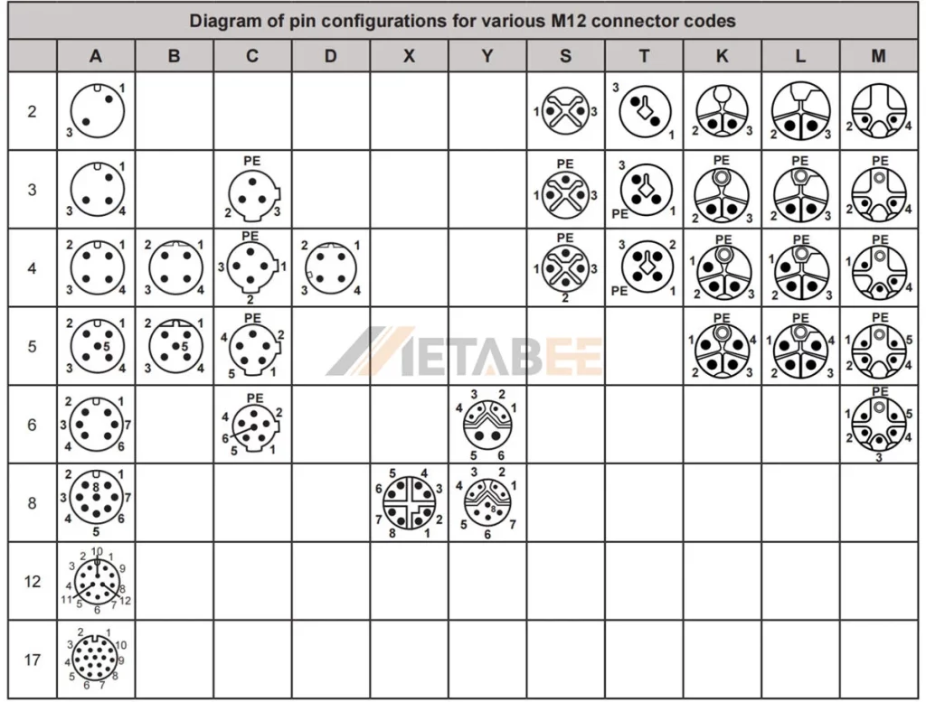
M12 connectors come in various codings, each with a unique pin configuration. Understanding the pinout, color code, and wiring diagram for your preferred coding type is critical for making correct connections. Here’s an overview of commonly used M12 connector types, along with their pinouts, color codes, and wiring diagrams:
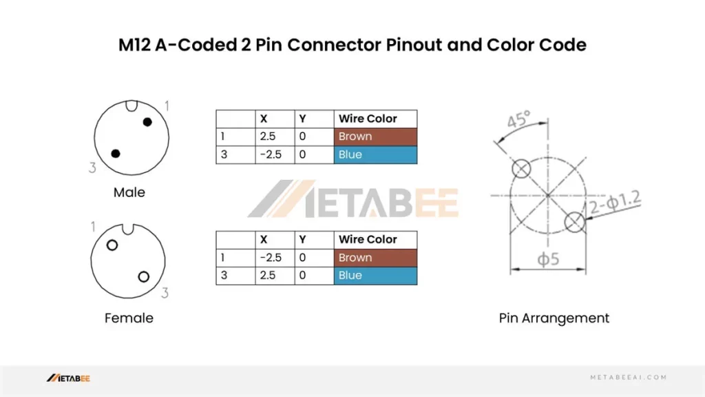
M12 2 Pin Connector Pinout and Color Code
A-coded M12 2-pin Male/Female Connector Pinout and Color Code
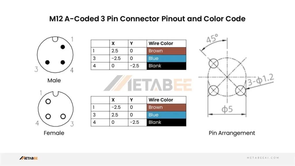
M12 3 Pin Connector Pinout and Color Code
A-coded M12 3-pin Male/Female Connectors Pinout and Color Code
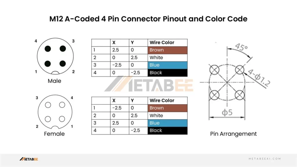
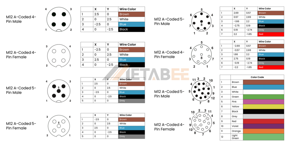
M12 4 Pin Connector Pinout and Color Code
A-coded M12 4-pin Male/Female Connectors Pinout and Color Code
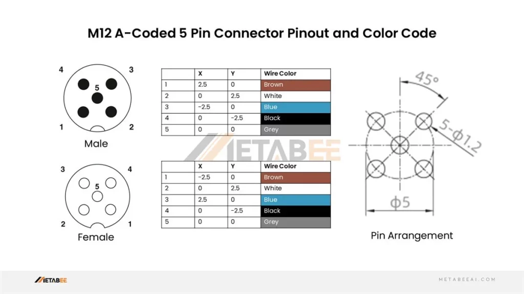
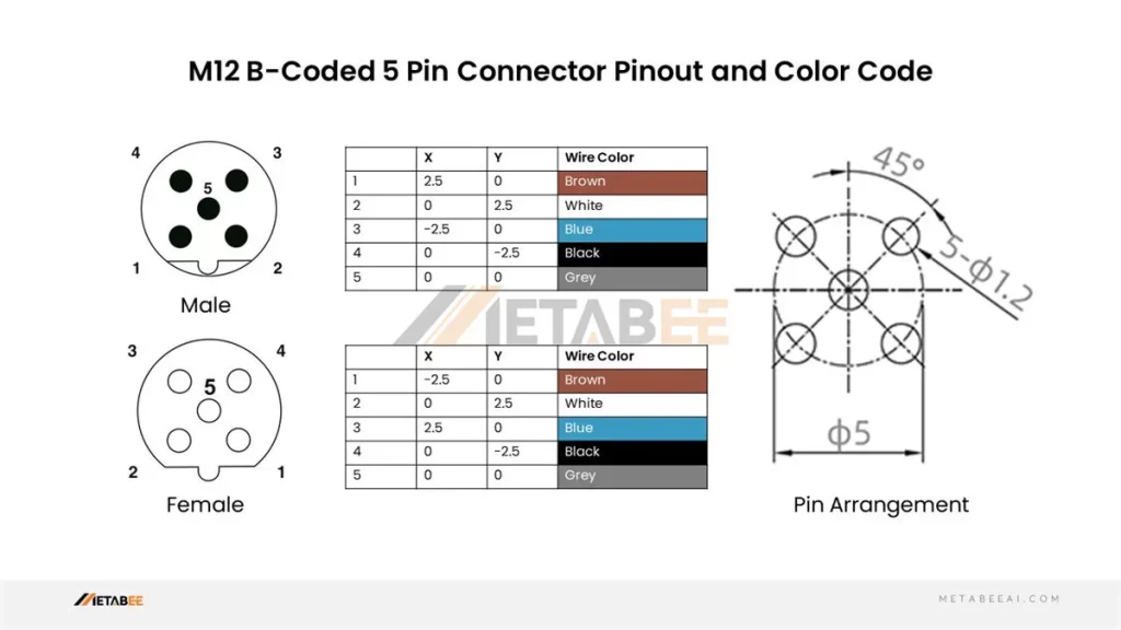
M12 5 Pin Connector Pinout and Color Code
A-coded M12 5-pin Male/Female Connectors Pinout and Color Code
B-coded M12 5-pin Male/Female Connectors Pinout and Color Code
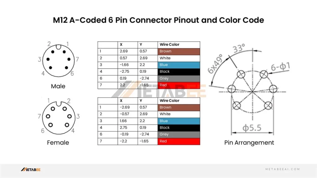
M12 6 Pin Connector Pinout and Color Code
A-coded M12 6-pin Male/Female Connectors Pinout and Color Code
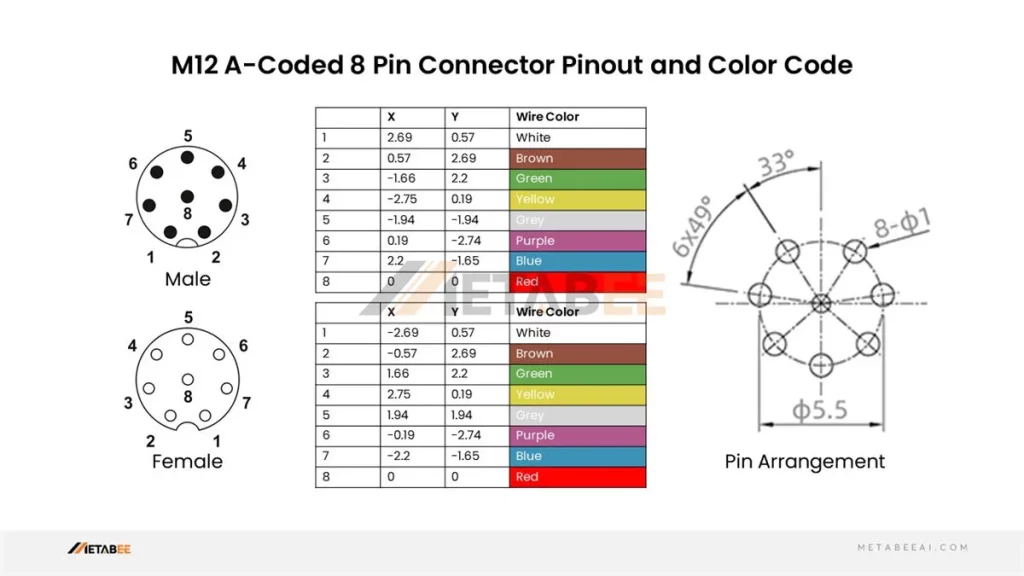
M12 8 Pin Connector Pinout and Color Code
A-coded M12 8-pin Male/Female Connectors Pinout and Color Code
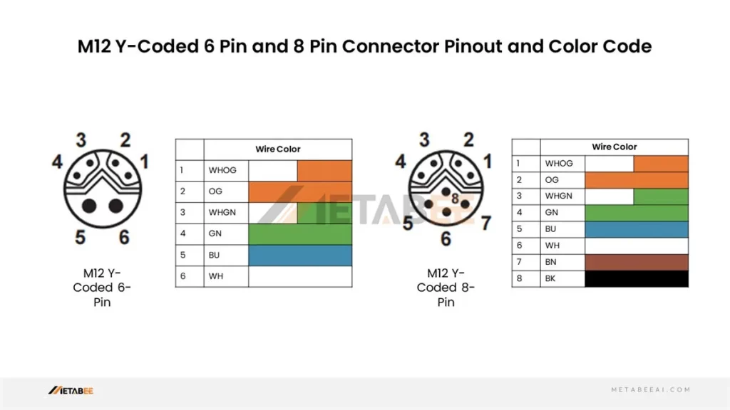
Y-coded M12 8-pin Male/Female Connectors Pinout and Color Code
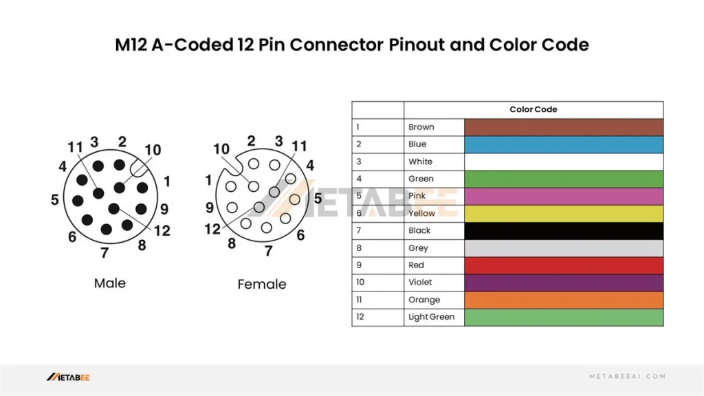
M12 12-pin Connector Pinout and Color Code
A-coded M12 12-pin Male/Female Connectors Pinout and Color Code
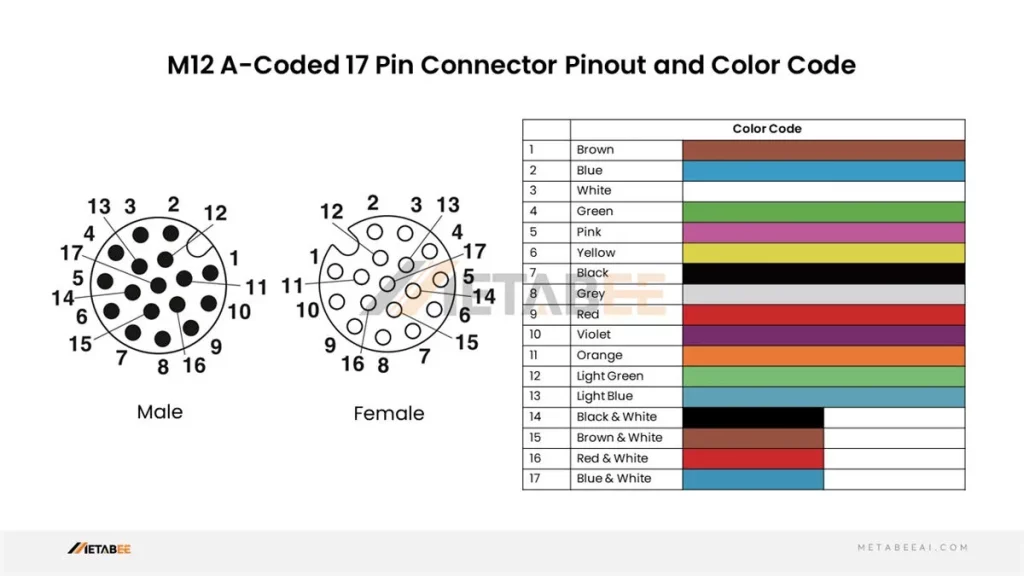
M12 17 Pin Connector and Color Code
A-coded M12 17-pin Male/Female Connectors Pinout and Color Code
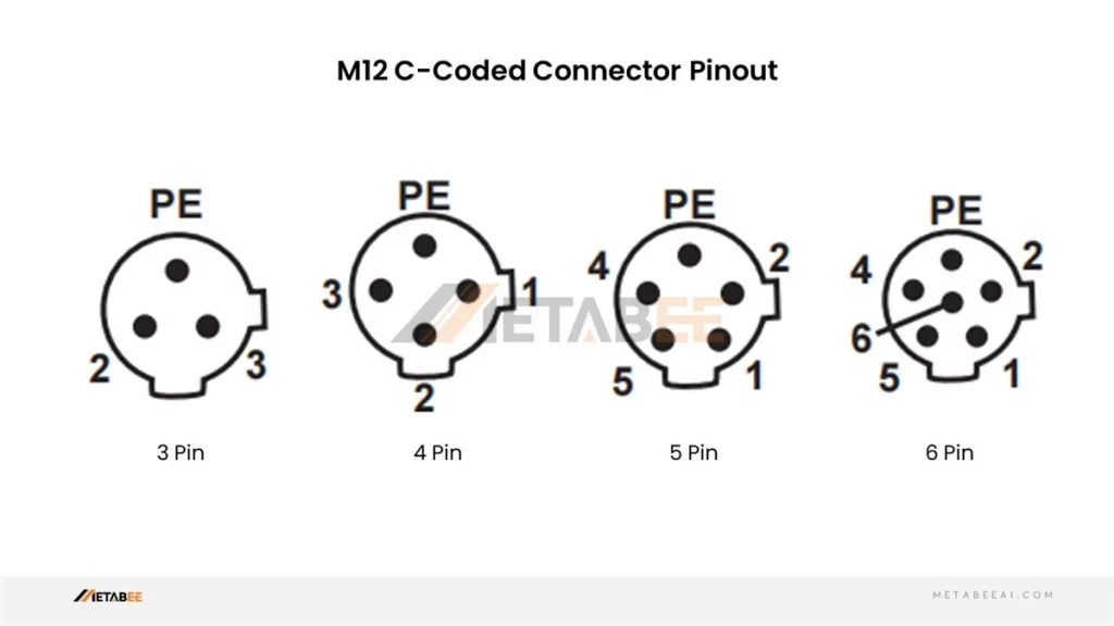
M12 C-coded Connector Pinout
C-coded M12 3-pin 4-pin 5-pin 6-pin Connectors Pinout
Understanding the pinout, color code, and wiring diagram for your chosen M12 connector type will enable you to build secure and dependable connections within your industrial automation system. The following section will explore common applications for M12 connectors and provide more information about M12 connector pinout.
M12 Connector Pinouts, Color Codes, and Wiring Diagrams for Applications
M12 connectors, with their versatility and robust design, are employed in a wide range of industrial automation applications. Here, we’ll look at specific wiring diagrams for some of the most common uses of M12 connectors:
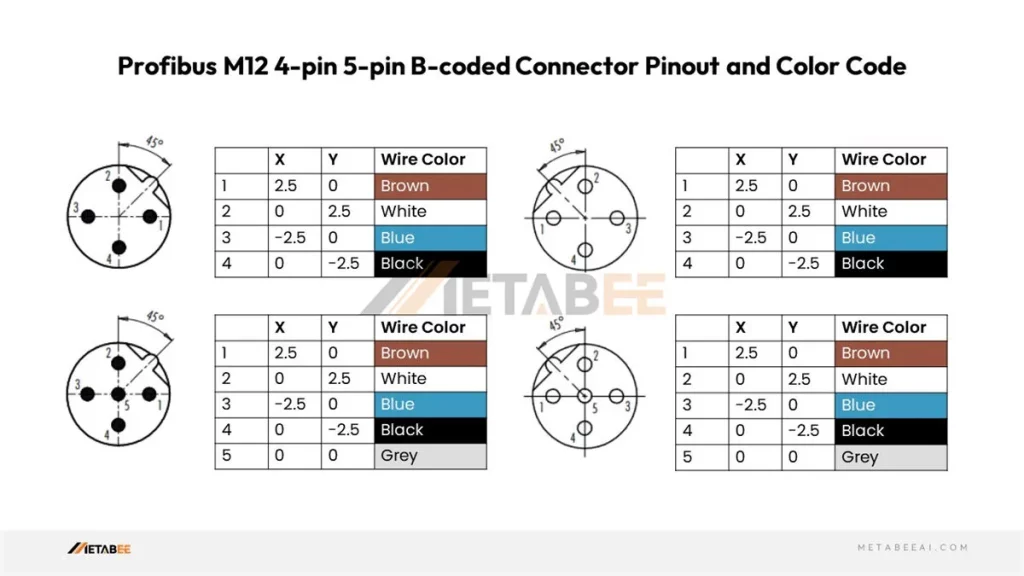
Profibus M12 Connector Pinouts, Color Codes, and Wiring Diagrams
Profibus M12 4-pin 5-pin B-coded Connector Pinout and Color Code
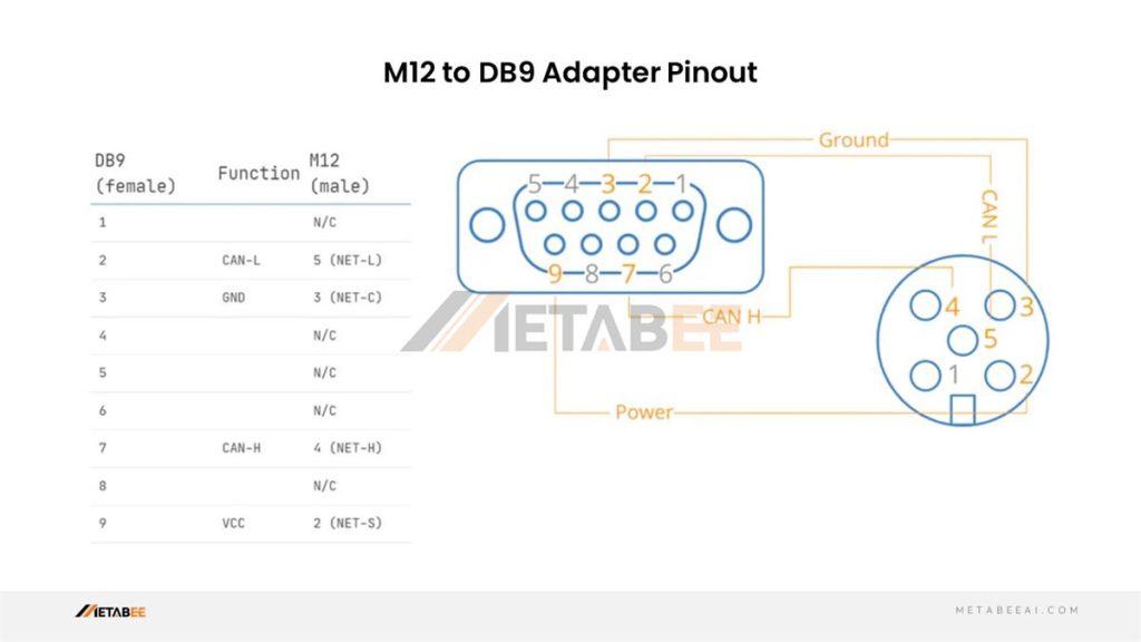
DB9 To A Coded Connector 5 Pin M12 Profibus Pinout and Wiring Diagram
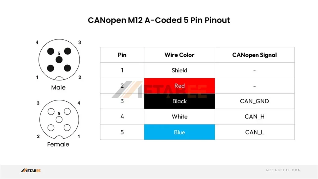
CANopen M12 Connector Pinout
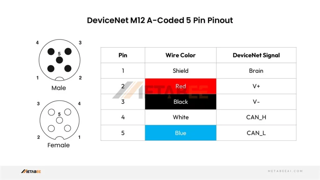
DeviceNet M12 Connector Pinout
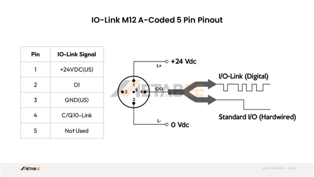
IO-link M12 Connector Pinout
M12 Sensor Connector Pinout, Color Codes, and Wiring Diagrams
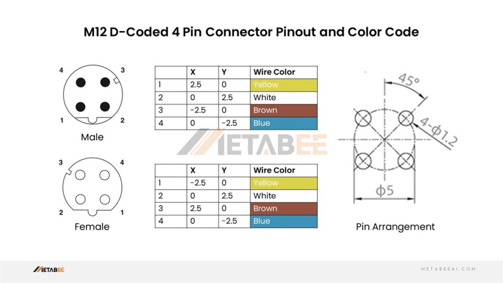
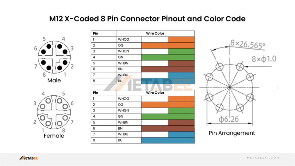
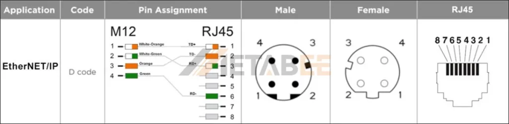
M12 EtherNet Connector Pinout, Color Codes, and Wiring Diagram
D-coded M12 4-pin Male/Female Connector Pinout and Color Code
X-coded M12 8-pin Male/Female Connector Pinout and Color Code
Ethernet D-coded M12 4 Pin To RJ45 Pinout And Wiring Diagram
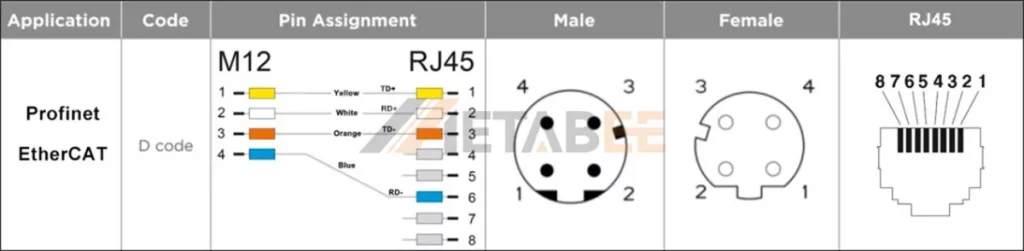
Ethernet/IP 4 Pin M12 D-coded To RJ45 Pinout And Wiring Diagram
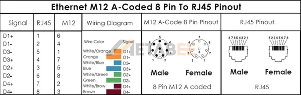
Industry Ethernet 8 Pin M12 A-coded To RJ45 Pinout
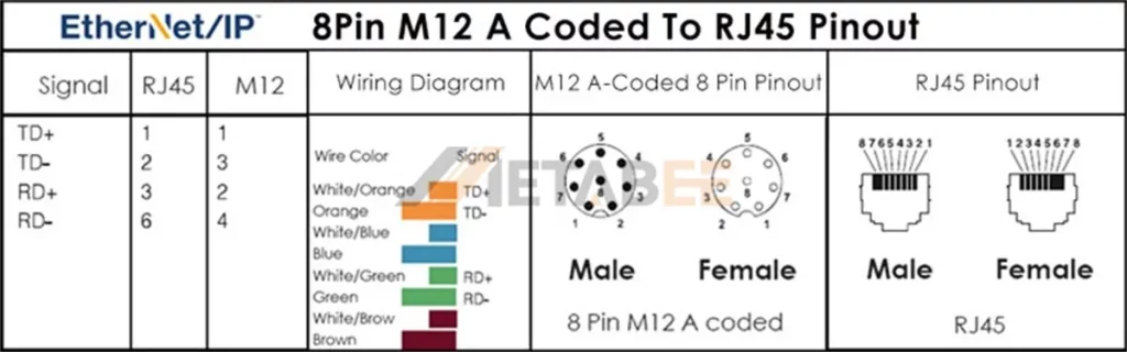
EtherNet/IP M12 A-coded 8 Pin To RJ45 Pinout
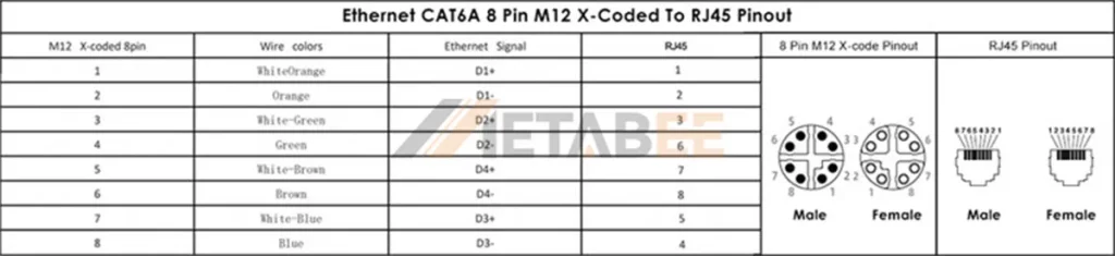
Ethernet CAT6A 8-pin M12 X-coded To RJ45 Pinout
M12 Power Connector Pinout
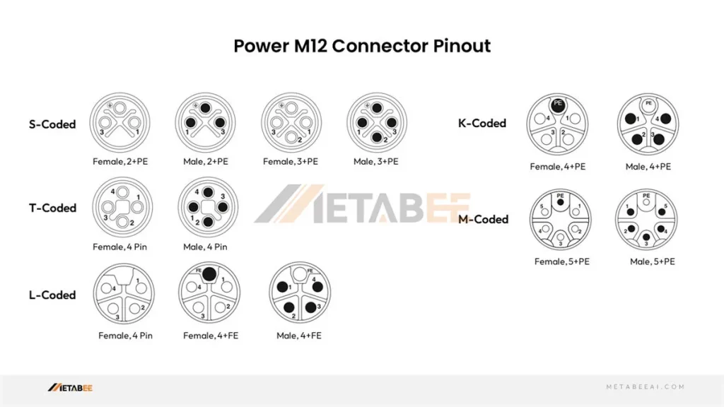
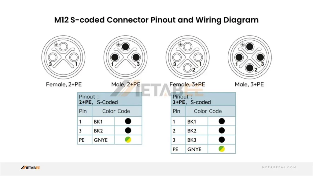
M12 S-coded Connector Pinout
S-coded M12 2-pin 3-pin 4-pin Connector Pinout and Color Code
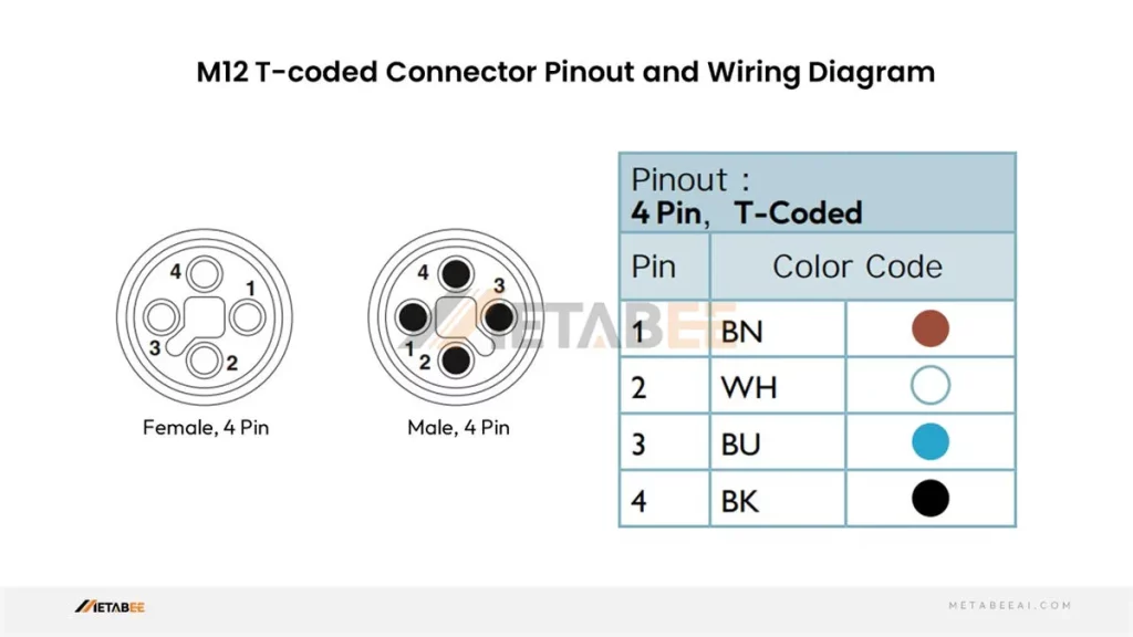
M12 T-coded Connector Pinout
T-coded M12 2-pin 3-pin 4-pin Connector Pinout and Color Code
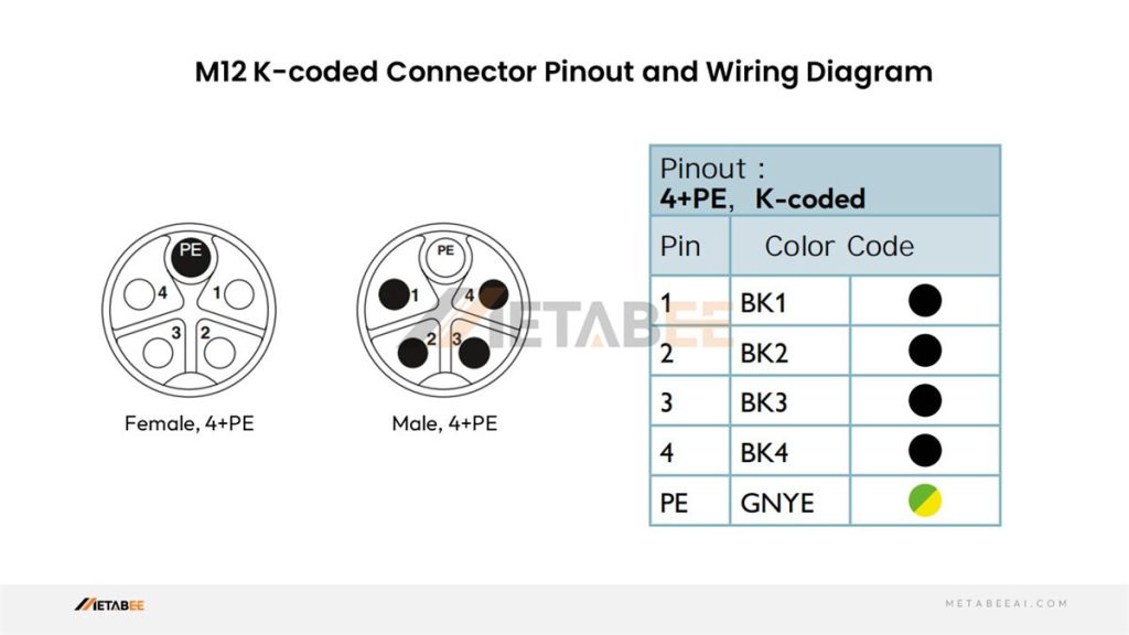
M12 K-coded Connector Pinout
K-coded M12 2-pin 3-pin 4-pin 5-pin Connector Pinout and Color Code
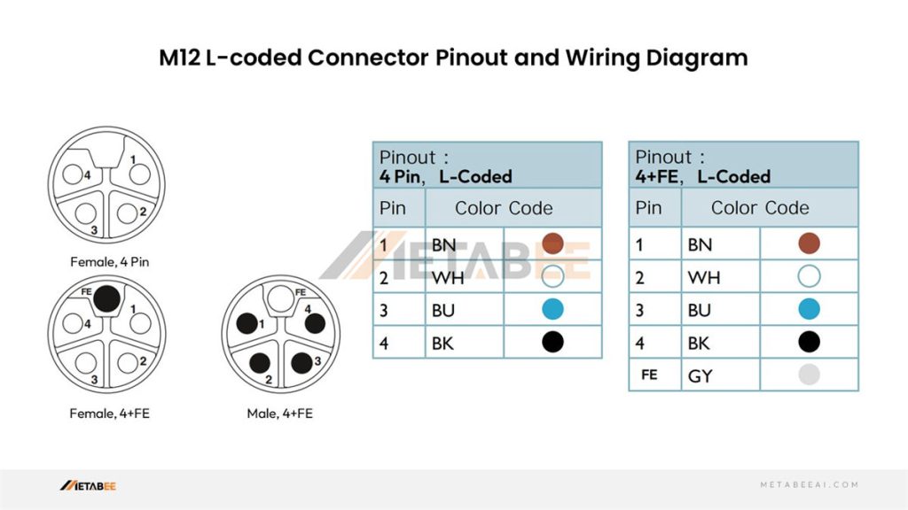
M12 L-coded Connector Pinout
L-coded M12 2-pin 3-pin 4-pin 5-pin Connector Pinout and Color Code
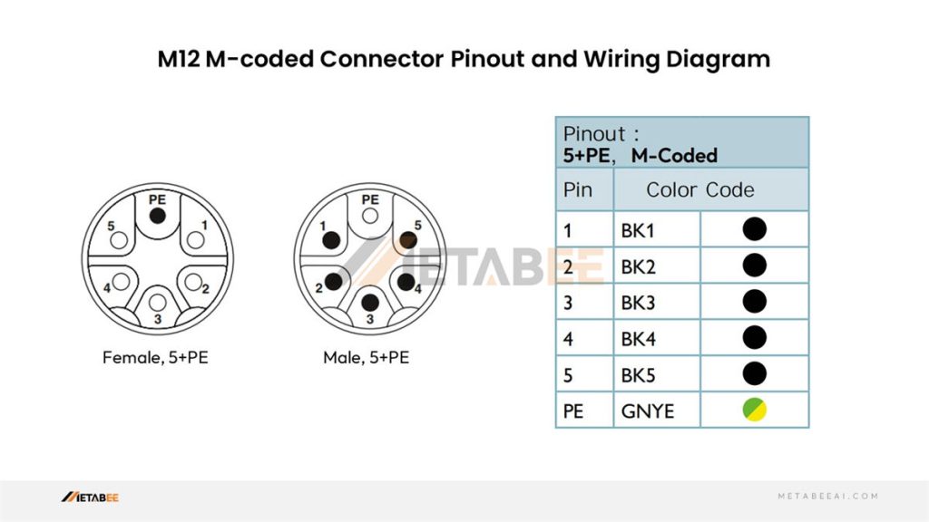
M12 M-coded Connector Pinout
M-coded M12 2-pin 3-pin 4-pin 5-pin 6-pin Connector Pinout and Color Code
Important Considerations When Working with M12 Connectors
M12 connectors provide a strong and user-friendly solution for industrial connections. However, a few important considerations can ensure a smooth and successful experience:
Double-Check the M12 Coding Type
M12 connectors come in various coding types, each with its pin configuration. Failure to identify the appropriate coding type for your application can result in incorrect connections and equipment damage. Always double-check the coding type (represented by letters such as A, B, C, D, and so on) before creating any connections.
Refer to Manufacturer’s Specifications
While this guide offers a general overview of M12 connector pinouts, color codes, and wiring diagrams, there can be variations between manufacturers. It’s crucial to read the manufacturer’s datasheets for your M12 connectors. These datasheets will provide the most accurate and up-to-date information regarding pinout, color code, and recommended wiring methods.
Use High-Quality M12 Connectors and Cables
The quality of your M12 connectors and cables directly impacts your connections’ performance and reliability. Metabee, a prominent connector manufacturer in China, is known for creating high-quality M12 connectors and cables. Ensure that the cables are specifically built for the application (e.g., power, data, etc.) and that the cable jacket material is appropriate for your environment.
Proper Tightening of the Connector
M12 connectors rely on a secure screw mechanism to provide a waterproof seal. Improper tightening can cause loose connections, corrosion, and signal integrity issues. Tighten the connector according to the manufacturer’s guidelines, which are normally hand-tight for M12 connectors.
Visual Inspection
Before connecting any M12 connectors, check them for physical damage, such as cracks in the housing, bent pins, or worn-out threads. Connectors that have been damaged should be replaced to ensure the integrity of the connection.
Cable Management
Proper cable management is critical for ensuring long-term reliability. Avoid excessive cable tension and severe bends, which might harm the internal wires. Use cable ties or other cable management methods to arrange and secure the cables for maximum performance.
By following these important considerations, you can ensure that your M12 connector installations are safe, dependable, and perform efficiently inside your industrial automation system.
Conclusion
Industrial automation systems rely heavily on the hidden heroes: M12 connectors. Their compact size, durability, and versatility make them ideal for establishing secure and reliable electrical connections in harsh environments. However, with various coding types, navigating the world of M12 connectors can be overwhelming.
This comprehensive guide has provided you with the knowledge to demystify M12 connectors. You’ve looked into their benefits, explored the different coding schemes, and acquired a strong understanding of pinouts, color codes, and wiring diagrams.
Muito bom o trabalho para identificação dos DIVERSOS CONECTORES M12 E SUAS FUNÇÕES DE ACORDO COM AS LETRAS, A, B,C,D, ,,,,,,
Yes, this way can effectively prevent mis-insertion.
Pingback: Unlocking the Secrets of M12 Connector Pin Configurations - connector manufacturer
Pingback: The 5 Non-Negotiable Parts for a Perfect NMEA 2000 Backbone - MetabeeAI