Heavy duty connector (HDC) solutions have become critical in modern industrial systems due to their durability, modular design, and ability to integrate both power and signal connections. To understand how they work, it is essential to look at their internal structure, which includes the housing, hood, inserts, and contacts. These components work together to ensure stable electrical performance.
Compared to standard connectors, heavy duty industrial connectors offer superior current-carrying capacity, mechanical durability, and environmental protection. Understanding their structure, types, and applications helps engineers and buyers make better decisions in system design and maintenance. This guide gives a clear overview of HDC connector components, types, applications, and selection tips for real-world projects.
- What Is a Heavy Duty Connector?
- Structure and Material of HDC Connector:
- Main Components of a Heavy Duty Connector
- Types of Heavy Duty Connectors
- Applications
- Selection Guide
- The Leading heavy duty connectors Factory and Manufacturer
- Conclusion
- Related Products
- FAQs
What Is a Heavy Duty Connector?
Definition
The Heavy Duty Connector (HDC) is a high-performance rectangular connector specifically engineered for harsh industrial environments. Unlike standard circular connectors, the HDC connector offers exceptional integration capabilities. It can simultaneously transmit power, data, and signals within a single, robust housing.
Thanks to this durability, the HDC connector has become an indispensable core component in robotics, automation lines, machine control, and energy storage systems.
Key Features and Advantages
HDC connectors have 6 main features, including:
- High Ingress Protection: Most units offer IP65, IP68, or even IP69K ratings, ensuring they are completely dust-tight and capable of withstanding high-pressure water jets.
- Rugged Construction: Die-cast aluminum or thermoplastic housings are engineered to withstand severe impact, vibration, and mechanical stress in harsh environments.
- Modularity: The system allows mixing power, signal, data, and pneumatics in a single frame, effectively saving space and simplifying complex cabling infrastructures.
- Secure Latching: Stainless steel locking levers provide a robust, vibration-proof connection that reliably prevents accidental disconnection during operation.
- Versatile Termination: Supports screw, crimp, and spring-clamp terminations to flexibly suit different installation requirements and maintenance preferences.
- Error-Proof Mating: Built-in polarization and coding pins prevent mismatched connections, ensuring safety and accuracy when using multiple connectors side-by-side.
Structure and Material of HDC Connector:
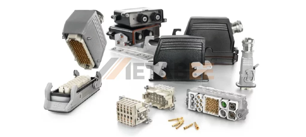
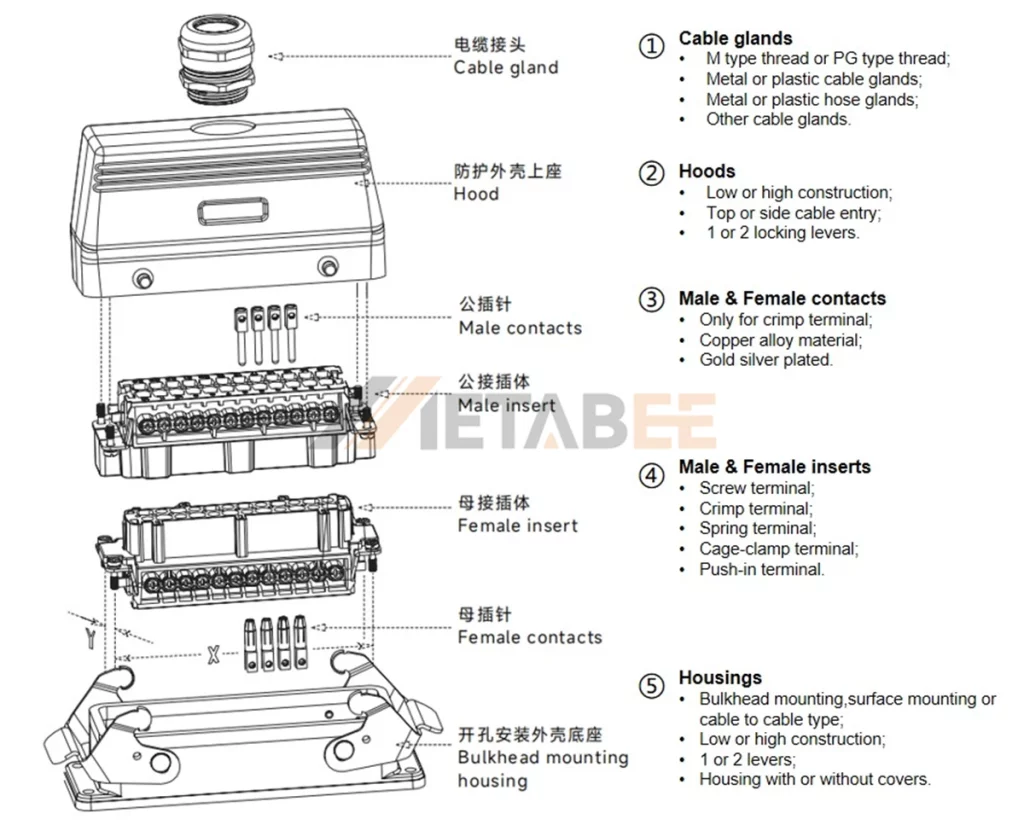
A heavy-duty connector is built from several coordinated parts that work together to deliver reliable electrical performance in harsh industrial environments. It consists of 5 main parts:
| Component | Material | Feature | Performance |
| Cable Glands | Body: Nickel-plated brass or Polyamide (PA6) Seals: PA/NBR | Thread Standards: Metric (M), PG | IP68 Protection Strain Relief Vibration Proof |
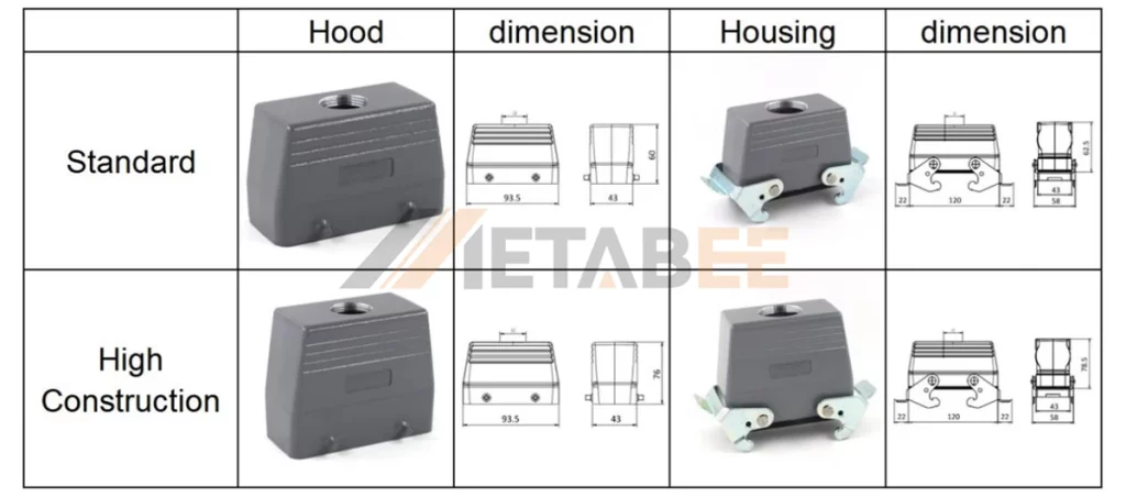
| Hoods | Shell: Die-cast aluminum alloy Surface Finish: Powder-coated (Standard RAL 7037 Grey) | Cable Entry: Top entry, Side entry Construction: Standard, High construction | High Impact Resistance Corrosion Resistance EMC Shielding |
| Contacts | Material: Copper alloy Plating: Hard silver plated or Gold plated | Termination: Crimp, Screw connection Current Capacity: Ranges from 10A to 200A+ | Low Contact Resistance High Mating Cycles Anti-Oxidation |
| Inserts | Body: Thermoplastic (PC) Flammability: UL94 V-0 | Termination: Screw, Crimp, Spring, Cage-clamp, Push-in Pin Count: Modular designs ranging from few pins to high-density | Electrical Insulation Temp Resistance |
| Inserts | Shell: Die-cast aluminum alloy Locking Levers: Stainless steel or Zinc-plated steel Seals: NBR | Mounting: Bulkhead, Surface mount, Cable-to-cable Locking System: Single lever, Double levers | Secure Locking IP65/IP66 Rating Ground protection |
Main Components of a Heavy Duty Connector
The overall structure helps us understand how a heavy duty connector operates, but deeper insight comes from examining its key components. Each part affects protection capability, electrical performance, and long-term durability. To give readers a clearer view of its construction, the following sections introduce these components one by one, starting with the housing and hood.
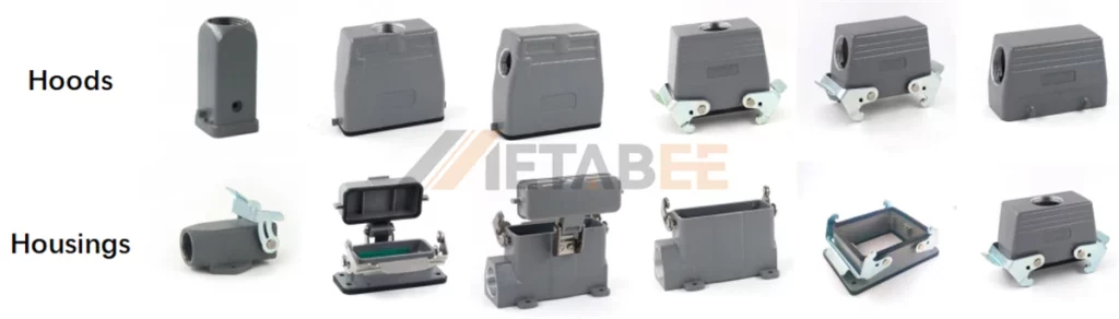
Housing and Hood
The “armor” of the connector system consists of the Hood (the top cover usually attached to the cable) and the Housing (the base attached to the machine or panel).
Example diagram of heavy-duty connector housing and hood
Material:
typically die-cast aluminum alloy with a powder-coated finish for corrosion resistance.
Locking Mechanism:
They feature stainless steel locking levers (single or double lever) that ensure a vibration-proof seal.
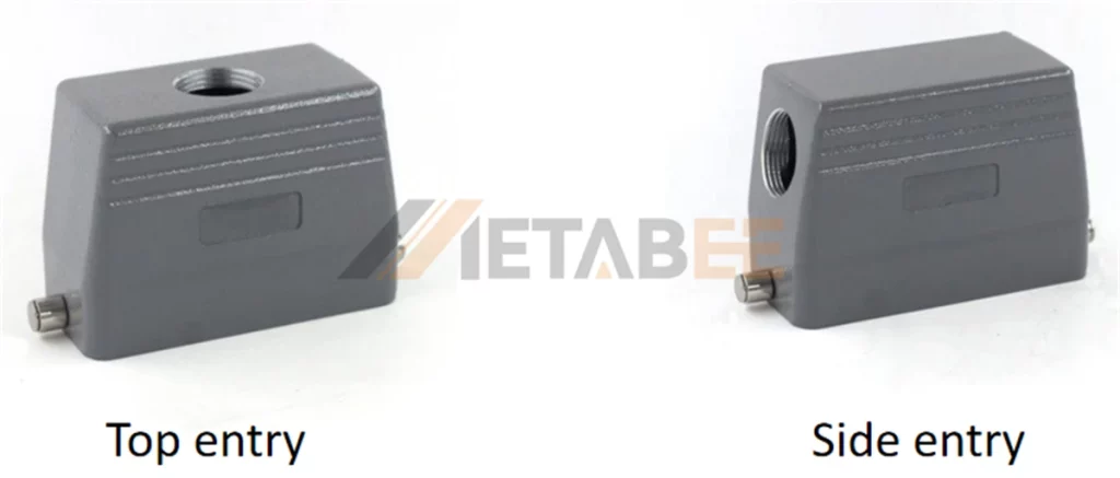
Entry:
Heavy duty connector hoods come in top-entry or side-entry configurations to suit cable routing needs.
Mounting Type:
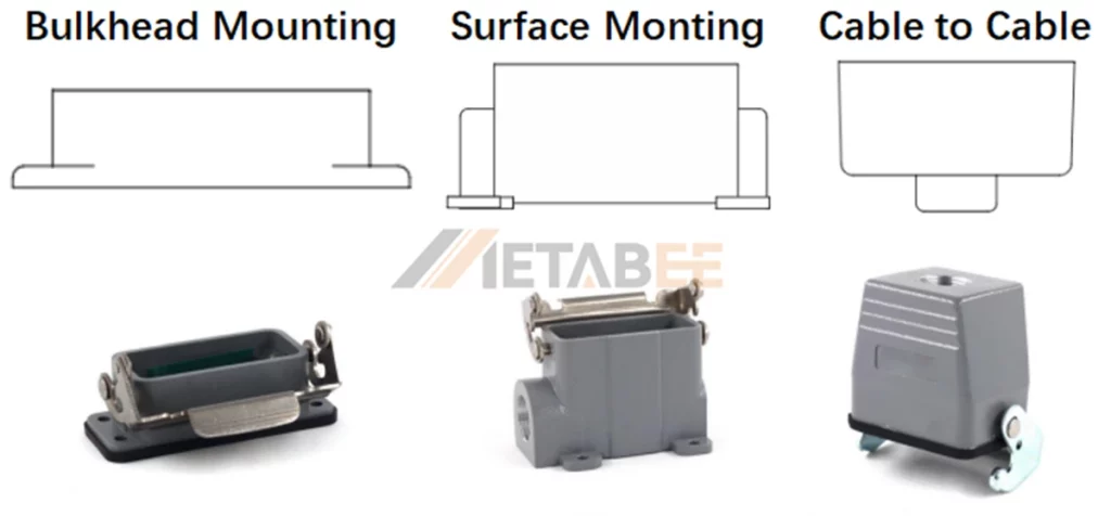
To suit different installation environments, the heavy-duty connector base housings are primarily available in three configurations. You can choose Bulkhead Mounting for panel feed-throughs, Surface Mounting for enclosed external boxes, or Cable-to-Cable for free-hanging connections.
Construction Profile:
Available in Standard and High Construction types. The “High” version offers increased internal volume, accommodating larger gauge wires or facilitating easier cable bending within the housing and hood.
At Metabee, our heavy-duty connector Housings and Hoods are built with reinforced locking latches that stay secure even during continuous vibration.
Housing and Hood Size Profiles
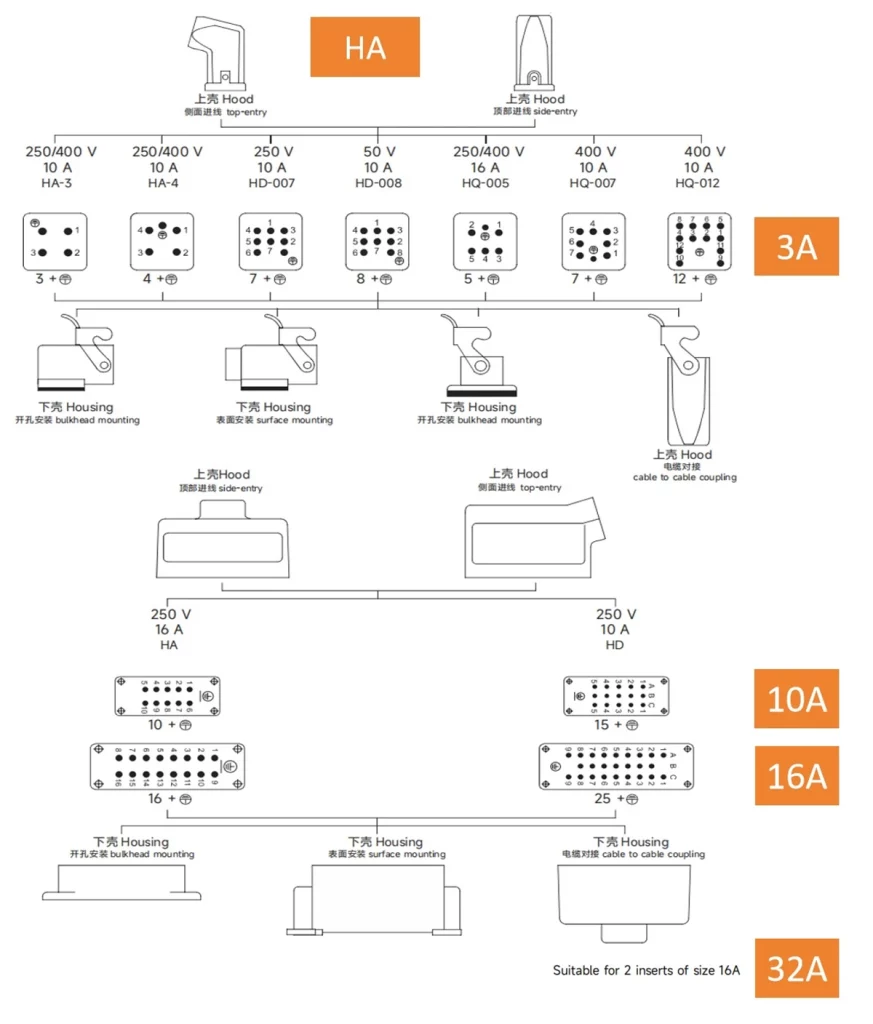
Housing and hood size are available in two width profiles, known as the A series and B series. Selecting the matching size for the insert ensures a proper fit and maintains stable electrical performance.
A Series Housing and Hood Matched Contact Insert
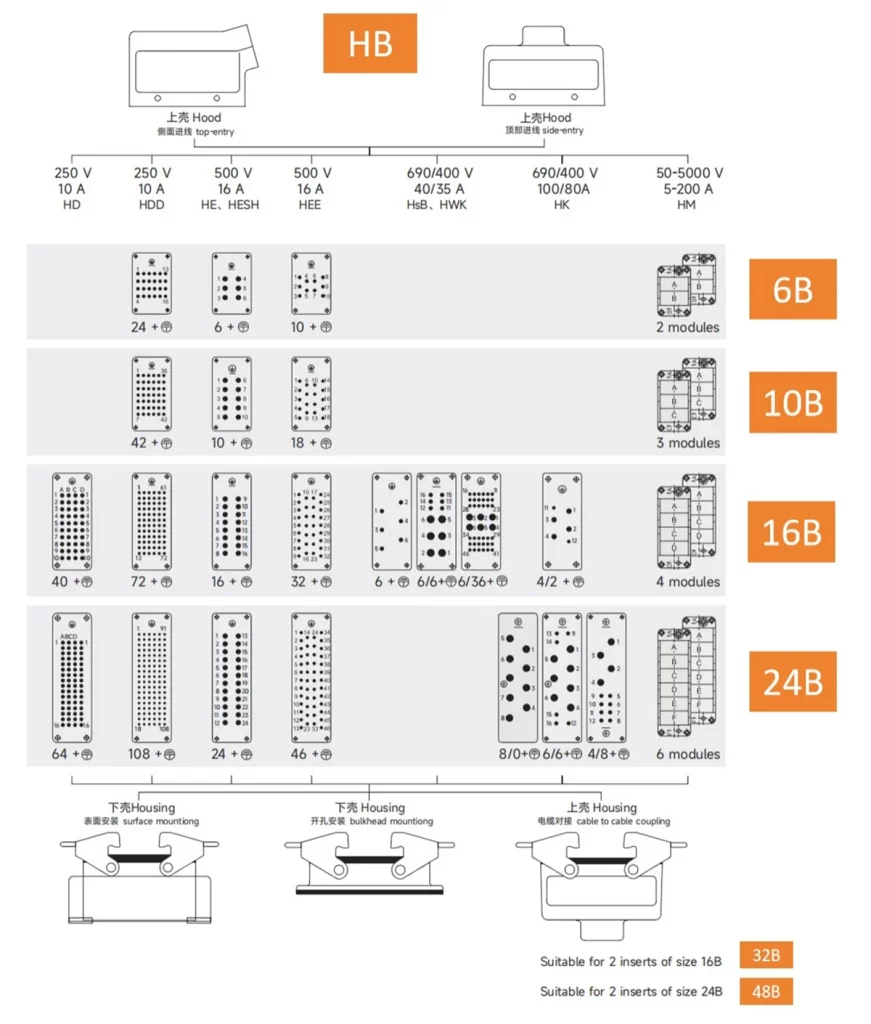
B Series Housing and Hood Matched Contact Insert
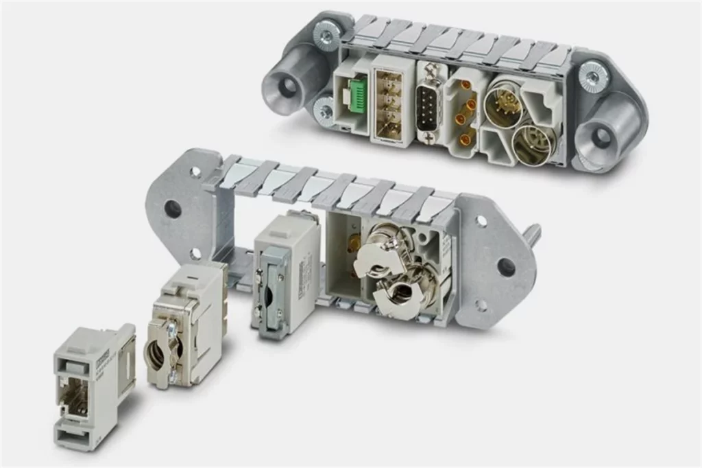
Heavy-Duty Connector Inserts
Insert is the insulating body that holds the electrical contacts. The male and female bodies are keyed to specific shapes, physically preventing incorrect mating.
Although all inserts use the same high-quality thermoplastic, their shapes differ to meet specific electrical and space requirements. As shown in the image below, Metabee offers a wide range of configurations:
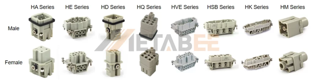
By observing the pin layout and housing shape, you can quickly identify the intended application of each series:
Compact Solutions (HA, HQ Series):
HA and HQ series are engineered to fit areas with limited space, such as compact motor connections and sensor housings.
The Industry Standard (HE, HVE Series):
The HE Series features the classic rectangular layout used globally for general machine control. The HVE Series looks similar but is internally structured to isolate contacts for higher voltage applications.
High Density (HD Series):
Packed with a large number of thinner pins, the HD series is designed to transmit complex signal arrays in a single connection.
High Current Power (HSB Series):
The HSB Series utilizes thicker, robust pins to carry heavy continuous currents (typically 35A). This design ensures stable power transmission for energy-intensive equipment like servo motors and industrial heaters without overheating.
Hybrid Functionality (HK Series):
The HK series offers hybrid functionality, providing a “2-in-1” solution. The insert layout combines large power pins and smaller signal pins, allowing power and control lines to run through a single connector.
Modular Flexibility (HM Series):
Shown on the far right is a single module component. These are designed to be snapped into a modular frame, offering the ultimate customization.
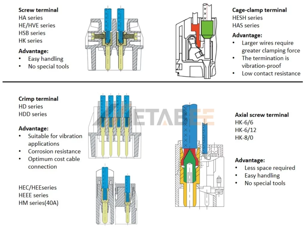
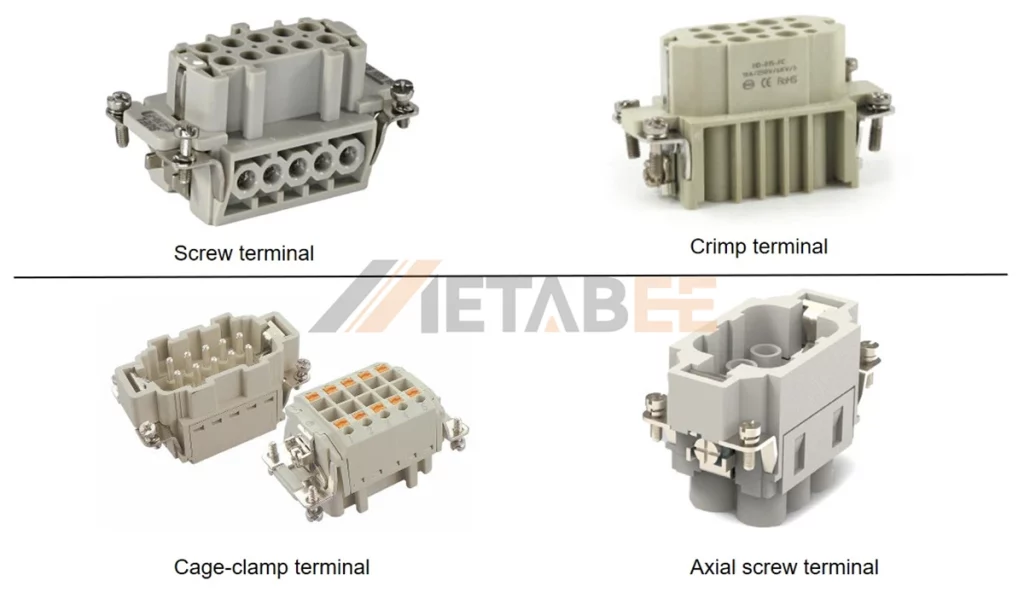
Termination Types of Insert
To accommodate diverse installation environments, vibration requirements, and tooling preferences, our inserts are designed with versatile connection options. The available termination technologies include Screw, Crimp, Cage-clamp, and Axial screw terminals. The figure below illustrates the compatible insert series and key advantages for each termination technology:
Structure and Material of HDC Connector Inserts
Knowing the insert’s physical structure is important for correct assembly. As shown in the diagram below, a standard insert typically consists of:
Heavy-duty connector inserts structure diagram(Screw Terminal Type)
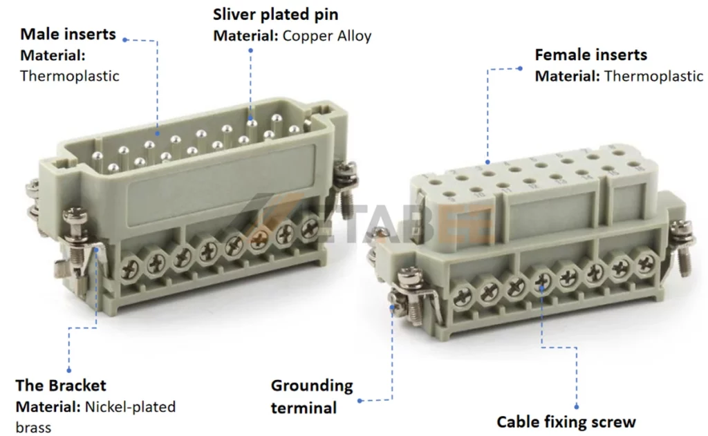
- Insulating Body —— Male and Female Inserts:
The body is made of self-extinguishing thermoplastic (UL94 V-0). This material is chosen for its high impact resistance and excellent dielectric properties, effectively isolating each contact.
- Conductive Contacts —— Pins and Sockets:
Depending on the insert type, contacts are either integral or detachable. They are machined from high-quality Copper Alloy. Silver or Gold plating is applied to minimize resistance and prevent oxidation.
- Grounding System—Bracket and PE Terminal:
Safety is critical. The insert features a Grounding Terminal integrated into a sturdy Bracket. Made from Nickel-plated brass, this bracket ensures a low-impedance path to the protective earth (PE), preventing electrical shock hazards.
- Wire Termination—Cable Fixing Screw:
Cable fixing screws allow wires to be securely clamped directly into the contact chamber. This design facilitates easy field installation and maintenance without the need for specialized crimping tools.
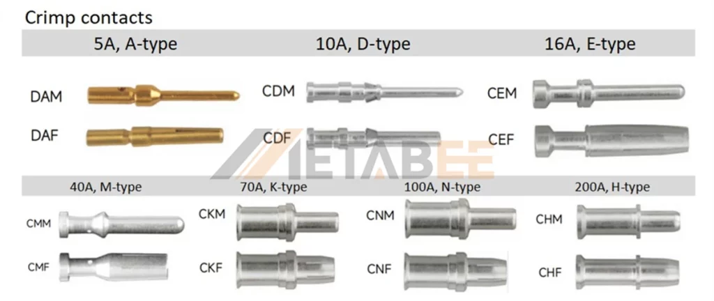
HDC Connector Contacts
Male and female contacts are the core conductive elements responsible for transmitting electricity across the connection interface. While some inserts feature fixed contacts, many utilize detachable crimp contacts to allow for flexible assembly.
- Material: Typically machined from high-grade Copper Alloy with Silver or Gold plating to minimize contact resistance and prevent oxidation.
- Current Rating: Designed for signal and power, typically ranging from 5A up to 200A.
Accessories and Tools
A complete assembly often requires:
- Cable Glands: Seals the cable entry for IP protection and secures the cable to prevent internal wires from loosening due to external pulling.
- Coding Pins: To prevent mating the wrong connectors when multiple identical connectors are used side-by-side.
- Crimping Tools: For secure wire termination.
Types of Heavy Duty Connectors
Engineers can choose from a vast array of configurations to suit specific industrial needs. To simplify selection, we classify connectors by three main criteria: internal structure, mounting type, and wire termination style.
Classification by Structure
Standard Heavy-duty Connectors
The Standard Series represents the industry’s “all-in-one” solution. Unlike modular systems, the series uses pre-configured inserts designed for specific power and density needs. It is the cost-effective choice when the application requires a fixed number of poles. Standard heavy-duty connectors include 2 series:
HE Series (Universal Standard):
The HE series is the all-purpose standard for industrial connectivity. It offers 6, 10, 16, 24, 32, or 48 pins with a rating of 16A / 500V. Due to its proven reliability and versatile pin options, it is the primary choice for connecting machine tools, conveyor systems, and control cabinets.
HA Series (Compact/Slim):
HA Series features a slim-profile design for tight spaces. Available in 3, 4, 10, 16, or 32 pins, it typically handles 10A or 16A (up to 250V). Its compact width makes it perfect for connecting small motors, sensors, and robotic joints where installation space is limited.
Modular Heavy Duty Connector
Modular systems (such as the HM modular inserts series) represent the modern evolution of industrial connectivity. Instead of a traditional fixed block, these systems utilize a customizable “Frame.” This design allows engineers to snap individual modules into the frame just like building blocks.
This innovative architecture delivers several critical advantages over fixed inserts:
- Ultimate Flexibility: A single heavy duty rectangular connector frame can simultaneously house a 200A power module, a Gigabit Ethernet module, and even a pneumatic air module.
- Space Saving: Reduces the need for multiple separate interfaces on the machine panel.
- Maintenance Speed: If a specific line fails, such as a damaged data pin, replace only that small module. This avoids changing the entire connector insert, reducing spare part costs and repair time.
Classification by Mounting Type
To adapt to different equipment layouts and wiring environments, Heavy Duty Connectors are classified into three distinct types based on their mounting interface:
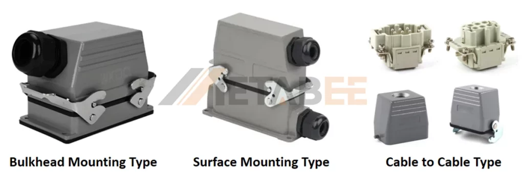
Bulkhead Mounting Type:
The most common configuration for control cabinets. The connector mounts directly to the panel surface, with wires passing through a cutout hole underneath. It offers the lowest profile and cleanest look.
Surface Mounting Type:
Ideal for applications where cutting a large hole in the machine is not possible. This type features a fully enclosed box that sits on top of the panel, with cable entry from the side.
Cable-to-Cable Type:
Designed for extension cords or joining two cables in mid-air. This type does not attach to any fixed surface, allowing for flexible, mobile connections.
Classification by Termination Style
Based on the method used to connect the wire to the contact, Heavy Duty Connectors are classified into 4 types:
- Screw Terminal: The most common and field-serviceable option. No special tools are required, though periodic torque checks may be needed in high-vibration environments.
- Crimp Terminal: Requires a specialized crimping tool. It offers the most gas-tight, vibration-resistant connection, making it the preferred choice for high-volume automated production.
- Cage-clamp and Push-in: Both belong to spring terminal technology, with vibration resistance as their core advantage. The standard Cage-clamp requires a screwdriver to open the spring for wire insertion. In contrast, the advanced Push-in variant enables direct, tool-free insertion of rigid wires.
- Axial Screw Terminal: Designed specifically for heavy power cables (e.g., 100A+). The screw is tightened from the top, driving a cone directly into the core of the wire strands. This design saves space (no side entry needed) and applies the immense pressure required for high-current transmission.
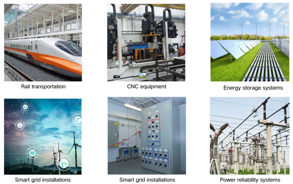
Applications
Heavy duty industrial connectors are widely used across diverse sectors that require reliable power and signal transmission. They are commonly found in hot-runner molds, robotics, automated production lines, CNC machinery, textile equipment, rail transportation, and power distribution systems. These connectors also support applications in energy, wind power equipment, and other environments where durable and secure electrical interfaces are essential. Their versatility allows them to meet a broad range of electrical and signal connection requirements in different industries and operating conditions.
Automation Systems and Assembly Lines
In automotive manufacturing, robots are frequently swapped out or reconfigured.
Using a modular heavy duty rectangular connector allows maintenance teams to disconnect a robot arm and replace it in minutes, minimizing downtime.
Machinery and Industrial Equipment
From injection molding machines to textile looms, these machines generate significant vibration. Metabee heavy duty Connectors are often used here to connect the main control cabinet to the motor drives and sensor arrays.
Robotics and Motion Control
Robots require a complex mix of high power (for motors), low voltage (for encoders), and data (for vision systems). A modular hdc connector is the standard solution to combine these into one interface at the robot base.
Power Distribution and Control Cabinets
For modular control centers, heavy duty power connectors allow for pre-wired sub-assemblies to be shipped separately and snapped together on-site, drastically reducing electrical contractor labor during installation.
Transportation, Rail, and Heavy Vehicles
Trains and construction vehicles are subject to constant shock, rain, and salt spray. Connectors used here must meet specific rail standards (like vibration and fire safety).
Energy, Solar, and Outdoor Industrial Equipment
Wind turbines and solar inverters are exposed to the elements. The UV resistance and IP68 waterproofing of high-quality heavy duty industrial connectors ensure that the power grid remains stable during storms.
Selection Guide
A heavy duty connector includes many components—housings, hoods, inserts, contacts, and cable glands. To choose the correct Heavy Duty Connectors for your project, you need to consider the following factors.
Current and Voltage Requirements
Start by confirming the maximum current and voltage of each circuit. This step defines the insert series and contact size you should use.
Different inserts support different current ratings, such as 10 A, 16 A, 35 A, or 40 A. High-power motors, heaters, and large loads require high-current inserts and matching contacts to maintain safe operation.
| Insert series | Rated Current | Rated Voltage | Typical applications |
| HA/HD/HDD series | 10A | 250V | Low-power control circuits |
| HQ series | 16A | 400V | Automation control systems |
| HE/HEE series | 16A | 500V | General industrial machinery |
| HVE series | 23A | 830V | High-voltage equipment |
| HSB series | 35A | 690V | Heavy industrial drives |
| HK series | 40/10A | 690/250V | Mixed-signal interfaces |
| HM series | 5A~200A | 50V~1000V | High-current power distribution |
Pin Number and Insert Type
Calculate the required number of poles based on the actual signals, control loops, and power lines of the system. Include the Ground/PE contact in your count and ensure the configuration aligns with the system wiring diagram. For example, a “6+PE” insert lists 6 poles in the model name but contains 7 actual contacts.
Choose between standard inserts or modular systems depending on your application. Standard inserts cover most general needs, while modular inserts fit systems that combine power, signal, and data in one interface.
Housings and Hoods Style
The housing and hood define the mounting method, entry direction, and environmental protection level.
- Protection level: Choose IP65 housings for general industrial environments. Select enhanced sealing structures if the equipment faces wash-down cleaning or outdoor exposure.
- Cable entry direction: Top entry works well for vertical layouts. Side entry suits compact spaces or horizontal routing.
- Locking system: Single-lever designs offer simple operation. Double-lever designs increase mechanical stability in high-vibration or outdoor applications.
Cable Specifications and Wiring Needs
- Cable Gland Sizing: Check the cable outer diameter when selecting the cable gland size—for example M20, M25, or PG21. A correct fit ensures proper sealing and strain relief.
- Wire Gauge: Confirm that the wire gauge (AWG or mm²) matches the contact termination range. For example, 10 A contacts fit smaller wires, while 40 A contacts require larger cross-sections.
- Wiring Efficiency: If your equipment requires fast installation or frequent disconnection, choose spring-clamp or push-in termination options to increase wiring efficiency and reduce maintenance time.
Professional Tip
Use the Metabee Heavy-Duty Connector Accessories to build your complete assembly online. This tool helps you match housings, inserts, contacts, and accessories correctly and reduces selection errors.
If you need further assistance with product selection, please contact our technical support team.
The Leading heavy duty connectors Factory and Manufacturer
Harting: The pioneer of the rectangular connector standard with the Han® series. They offer the industry’s widest range of modular systems and are the quality benchmark for robotics, rail, and wind energy.
TE Connectivity: A global leader offering extremely robust HDC solutions. Compliant with all major international standards (IEC, UL), their connectors are a top choice for machine builders worldwide requiring maximum reliability.
Weidmüller: Renowned for the RockStar® series and innovation in termination technology. Their advanced “PUSH IN” systems and modular frames significantly reduce wiring time for control cabinet assembly.
Metabee: A rising star engineered as the perfect alternative to top-tier brands. Their HDC series are 100% compatible with Harting and TE standards, offering shorter lead times and superior price-performance. The ideal partner for OEMs optimizing supply chain agility.
Renhotec: Known for a wide range of industrial and RF connectivity. They offer reliable heavy duty connector solutions and excel in providing flexible, custom cable assemblies to meet specific automation requirements.
Conclusion
The core value of heavy duty connectors is clear. They keep power and signal transmission stable and safe under high load, strong vibration, electrical noise, and harsh environments. Their robust housings, wide electrical ratings, and modular configuration options allow engineers to build systems that are both reliable and easy to maintain.
As Industry 4.0 continues to evolve, the demand for smart, robust, and hybrid heavy duty industrial connectors will only grow. Choosing the right partner and the right specifications today will future-proof your machinery for tomorrow.
For complete product details and configuration options, visit the Metabee Heavy Duty Connector.
Related Products
- Heavy-Duty Connectors
- Heavy-Duty Connector Inserts, Modules
- HM modular inserts series
- Heavy-Duty Connector Contacts
- Heavy-Duty Connector Accessories
- Heavy-Duty Connector Assemblies
- Heavy-Duty Connector Housings, Hoods
FAQs
Q1: What is the difference between an HDC connector and a Harting connector?
A: “Harting” is a brand name that became synonymous with the product type, much like “Kleenex” for tissues. An hdc connector is the generic technical term.
Q2: Can I mix power and data in one heavy duty rectangular connector?
A: Yes! By using a modular frame system, you can insert a data module (RJ45) right next to a power module in the same housing, keeping them shielded and secure.
Q3: How do I know which IP rating I need?
A: For general indoor factory automation, IP65 is usually sufficient (dust-proof and splash-proof). For outdoor use or wash-down areas (food & beverage), look for IP68 or IP69K.
Q4: Are heavy duty power connectors safe to disconnect under load?
A: Generally, no. Most industrial connectors are not designed to function as switchgear. You should always isolate the circuit before decoupling to prevent arcing, unless the connector is specifically rated with breaking capacity.
Q5: Do I really need specialized tools for Crimp Terminal inserts?
A: Yes. Proper crimping tools are essential to ensure a vibration-proof connection. If you do not have these tools, we recommend using Screw or Push-in terminals instead.
Q6: When should I choose a “High Construction” hood?
A: Choose High Construction housings if you are working with thick cables or need extra internal space for complex wiring. For standard applications, the regular height is sufficient.