
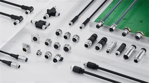
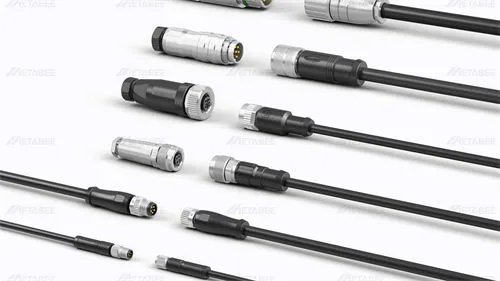

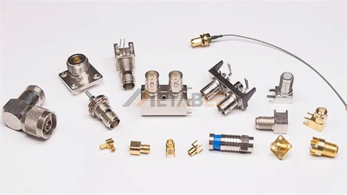

BNC connectors are widely used in RF, video, test and measurement, and communication systems. Their compact size, bayonet locking mechanism, and reliable signal performance make them suitable for many coaxial cable applications.
BNC connectors come in a multitude of configurations, each types serves a distinct electrical or mechanical purpose. Manufacturers offer various BNC connector types based on impedance, mounting method, cable compatibility, orientation, and application requirements.
This guide explains the main BNC connector types. It also provides several factors for selecting the right BNC connector types for Engineers and procurement teams.
What is BNC Connector
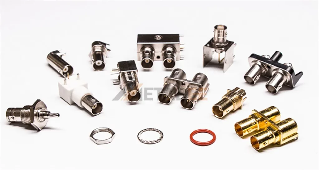
BNC (Bayonet Neill–Concelman) is a miniature RF coaxial connector with a bayonet-style locking mechanism. It provides fast, secure connections for RF signal transmission in telecommunications, test equipment, video systems, and wireless applications.
BNC connectors are available in different impedances, terminations, mounting styles, and configurations. Understanding these differences is essential when selecting the right connector for a specific cable, frequency range, and application.
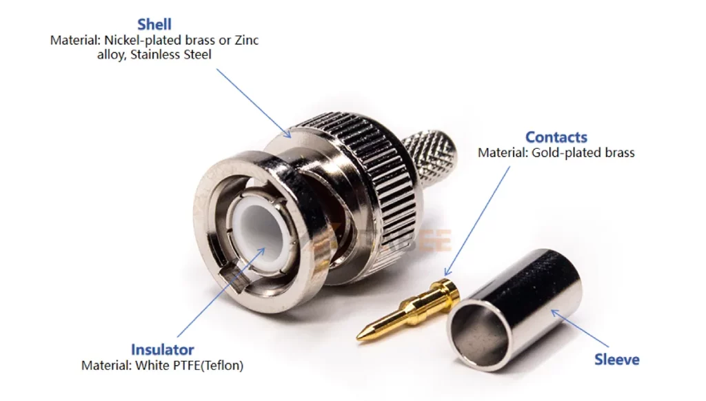
Structure
- Center Contact (Pin or Socket): Carries the RF signal. Manufacturers usually construct it from brass plated with gold.
- Dielectric Insulator: Holds the center pin in place and isolates it from the outer ground shield. Engineers primarily use PTFE(Teflon).
- Shell: Conducts the return path current and provides RF shielding. It is typically made of nickel-plated brass or zinc alloy, stainless steel.
- Bayonet Sleeve: Maintains axial tension against the mating jack to keep the ground contacts firm.
BNC Connector Types: 5 Common Classification Methods
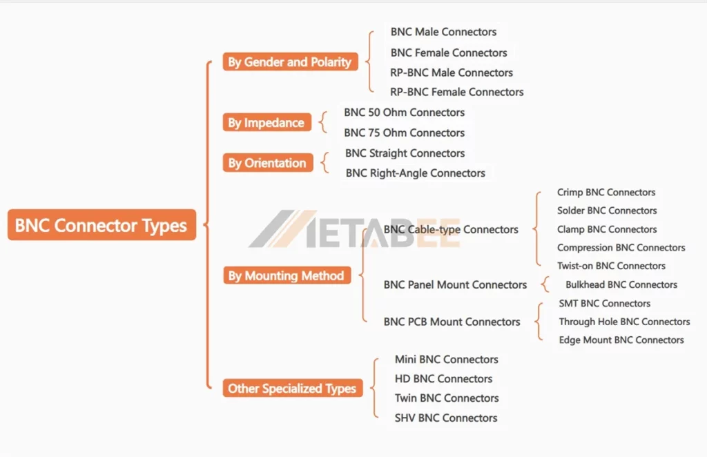
Engineers classify BNC connectors into 5 main types according to gender and polarity, impedance, mounting method, connector orientation and other special types. Each classification represents a different design consideration. Understanding these categories helps to select connectors based on system requirements.
Detailed BNC Connector Types at a Glance
| Classification | BNC Connector Types | When to Choose / Typical Applications |
| By Gender and polarity | BNC Male, BNC Female, RP-BNC Male, RP-BNC Female | Choose based on the mating interface and signal polarity requirements; common in RF, test equipment, and coaxial connections. |
| By Impedance | 50 Ohm, 75 Ohm | 50 Ohm: RF, wireless, and test equipment. 75 Ohm: video, broadcast, CCTV, and TV systems. |
| By Mounting method | Cable type, Panel mount, PCB mount | Cable type: cable assemblies. Panel/Bulkhead: equipment interfaces. PCB Mount: embedded electronic devices. |
| By Connector orientation | Straight, Right angle | Straight for standard routing; right angle for space-limited applications |
| By Specialized Design | Mini BNC, HD BNC, Twin BNC, SHV BNC | For high-density, high-bandwidth, multi-channel, or high-voltage applications |
For most applications, the most important specifications are impedance, cable compatibility, mounting method, termination method, frequency range, and environmental requirements.
Types of BNC Connectors by Gender and Polarity
BNC connectors are commonly classified by gender and polarity. The connector interface determines how devices connect and how signals are transmitted.
BNC Male Connector
A BNC male connector features a protruding center pin and an outer bayonet locking structure. The male BNC connector connects with a female jack using a quarter-turn locking mechanism. The center pin carries the signal, while the outer shell provides shielding and mechanical connection. BNC male connectors are commonly used on coaxial cables. Examples include RG58, RG174, RG316, and RG59 cable applications.
BNC Female Connector
A BNC female connector contains a hollow contact designed to accept the male center pin. Female connectors are standard on oscilloscopes, signal generators, network analyzers, and video switchers. Bulkhead and PCB variations also utilize female interfaces.
RP-BNC Male Connector
RP-BNC male connectors are reverse-polarity BNC connectors with a male interface, designed for secure coaxial connections while maintaining the familiar bayonet locking mechanism. They are commonly used in wireless, RF, and antenna systems where reverse-polarity configurations are required.
When selecting an RP-BNC male connector, verify both the mechanical interface and center-contact configuration.
RP-BNC Female Connector
RP-BNC female connectors have a female mechanical interface but use a male center pin. This configuration reverses the center contact compared with a standard BNC female connector.
The key distinction is that RP-BNC male and female refer to the outer mechanical interface, while RP-BNC refers to the reversed center contact.
BNC VS RP-BNC
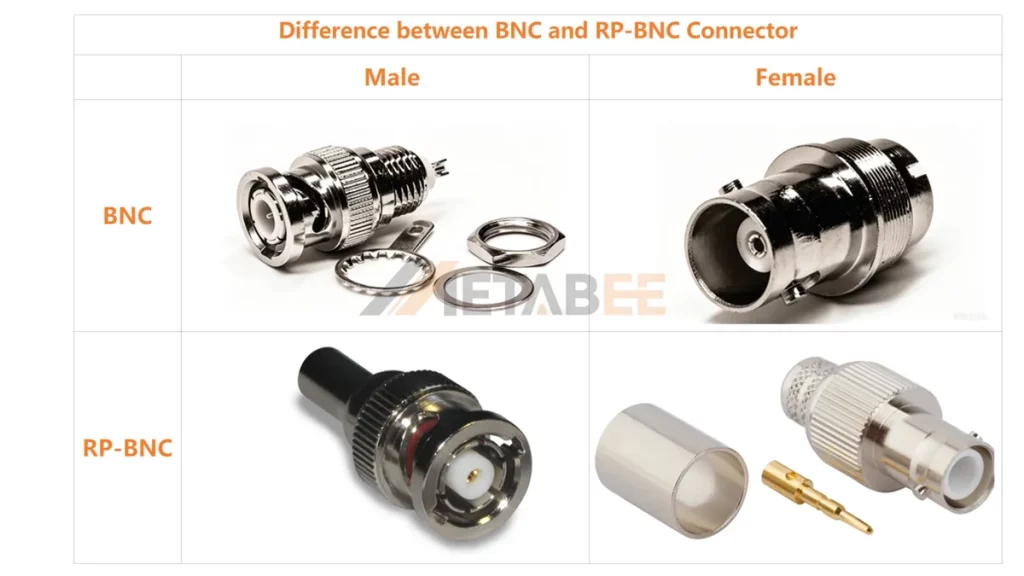
The main difference between standard BNC and RP-BNC connectors is the center contact configuration.
| Type | Center Contact | Mechanical Interface |
| Standard BNC Male | Pin | Male plug |
| Standard BNC Female | Socket | Female jack |
| RP-BNC Male | Socket | Male plug |
| RP-BNC Female | Pin | Female jack |
RP-BNC reverses the center-contact gender while retaining the corresponding mechanical interface.
Standard BNC connectors provide general-purpose connectivity. RP-BNC connectors provide interface control to avoid incorrect unintended connections. Using a standard BNC connector with an RP-BNC interface will result in improper electrical contact or no connection.
Types of BNC Connectors by Impedance
Impedance is one of the most important specifications when selecting a BNC connector. RF circuit design requires matching connector impedance to transmission lines. Mismatched impedance creates signal reflections. These reflections increase the Voltage Standing Wave Ratio (VSWR).
BNC 50 Ohm Connector
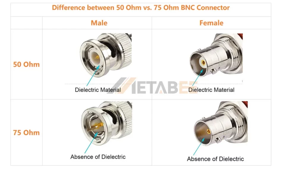
50-ohm BNC connectors are mainly designed for RF and microwave applications. It optimizes power transfer efficiency in wireless networks, test equipment, and legacy Ethernet networks. The 50 Ohm interface features a relatively thick center pin and dielectric material extending into the interface mating face. It functions up to 4 GHz with minimal return loss.
Common applications include:
- Wireless communication systems
- RF testing equipment
- Antenna connections
- Laboratory instruments
- Data communication systems
BNC 50-ohm connectors typically work with 50-ohm coaxial cables such as RG58, RG174, RG316
and RG400.
BNC 75 0hm Connector
75-ohm BNC connectors are mainly used for video and broadcast applications. The 75 Ohm interface uses a smaller center pin. They are designed for systems using 75-ohm coaxial cables.
Typical applications include:
- CCTV systems
- Broadcast video equipment
- Digital video interfaces
- Professional camera systems
75-ohm BNC connectors usually work with cables such as RG59 and RG6.
50 Ohm vs. 75 Ohm BNC Connector: What’s the Difference?
The main difference between 50-ohm and 75-ohm BNC connectors is their characteristic impedance.
| Feature | 50 Ohm BNC | 75 Ohm BNC |
| Typical applications | RF, test & measurement | Video, broadcast |
| Common cables | RG58, RG174, RG316 | RG59, RG6 |
| Typical equipment | Signal generators, VNAs | Cameras, monitors |
| Primary design goal | RF power transfer / matching | Low attenuation/video transmission |
| Frequency considerations | RF systems | Video / SDI systems |
| Connector geometry | Different interface geometry | Different interface geometry |
The BNC connector impedance should match the cable and equipment impedance to minimize signal reflections and maintain signal integrity.
Types of BNC Connectors by Mounting Method
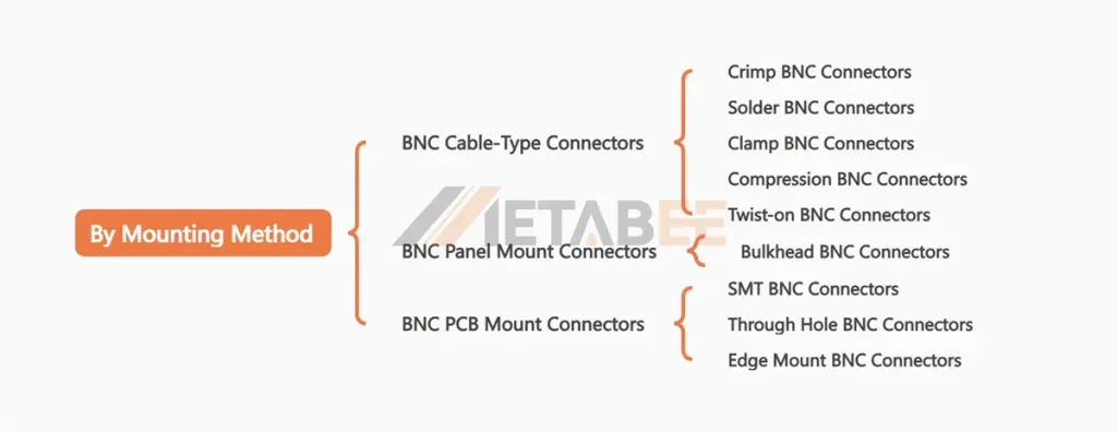
The mounting method determines how a BNC connector attaches to cables, equipment panels, or printed circuit boards. Engineers select the mounting style based on mechanical structure, assembly process, maintenance requirements, and available installation space.
Each type has different mechanical features and termination methods.
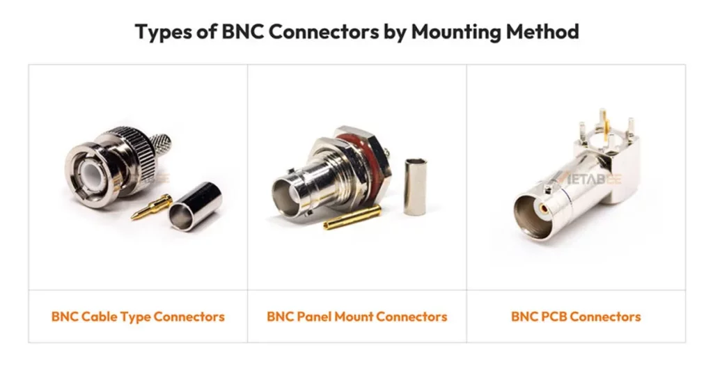
Cable-Type BNC Connector
Cable-type BNC connectors are installed directly onto coaxial cables. They are commonly used for detachable cable assemblies, test leads, and equipment interconnections.
The connector termination method affects installation time, mechanical strength, and electrical performance. Including:
- Crimp BNC Connectors
- Solder BNC Connectors
- Clamp BNC Connectors
- Compression BNC Connectors
- Twist-on BNC Connectors
The termination method should match the coaxial cable construction, installation conditions, and required mechanical strength. For high-volume production, crimp BNC connectors are often preferred, while solder and clamp types suit low-volume or field applications.
Crimp
BNC Crimp connectors are one of the most common cable termination types. Engineers utilize a metallic ferrule compressed around the coaxial shield braid using a calibrated crimp tool. The center pin can be soldered or crimped using precision die sets.
Advantages:
- Fast assembly
- Consistent termination quality
- Good mechanical strength
- Suitable production efficiency
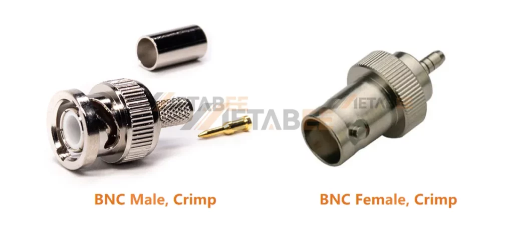
Disadvantages: Requires specialized crimping tools and exact hex die sizes for each cable type.
Solder BNC
BNC Solder connectors require soldering the center conductor to the center pin. Technicians often solder or mechanically clamp the outer shield braid.
Advantages:
- Reliable electrical connection
- Easy inspection and repair
- Suitable for low-volume production
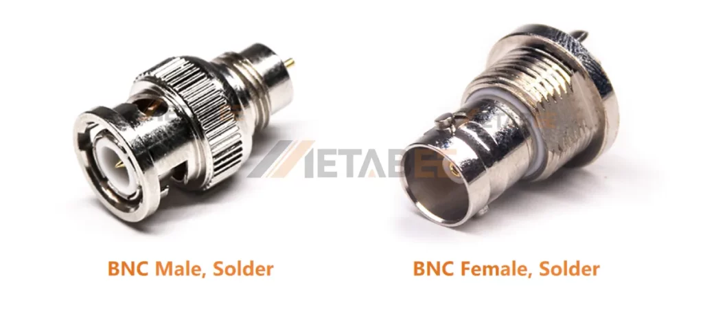
Disadvantages: Slower assembly speed. Excessive heat can distort the internal PTFE dielectric.
Clamp BNC
Clamp bnc connectors use internal threaded metal collars, pressure washers, and silicone gaskets. Engineers thread the rear compression nut forces a internal brass taper ring against the coaxial braid.
Advantages:
- Tool-free or low-tool installation
- Easy replacement
- Good mechanical retention
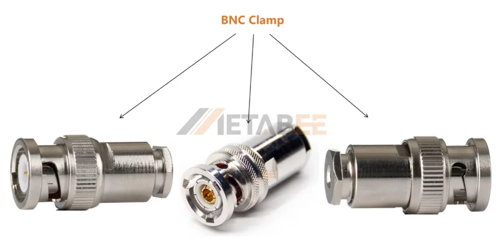
Disadvantages: Contains multiple small internal loose parts. Higher labor cost per termination.
Compression BNC
BNC compression connectors use a continuous 360° radial compression sleeve. Pushing an internal cone under the cable jacket creates an airtight, waterproof seal.
Advantages:
- Excellent shielding performance
- Strong pull resistance
- Reliable environmental protection
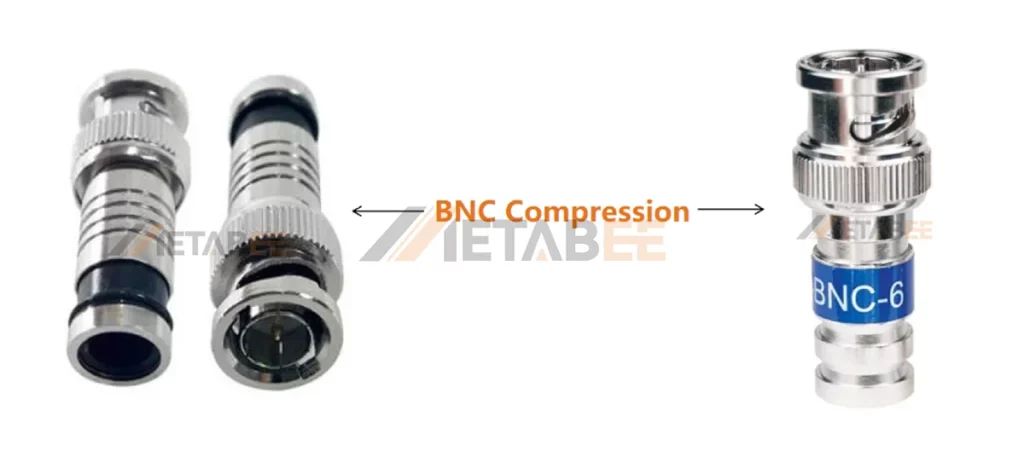
Disadvantages: Requires proprietary linear compression tools and matching cable stripping dimensions.
Twist-on BNC
Twist-on bnc connectors feature internal spiral threads inside the rear barrel. Technicians strip the cable and screw the connector body directly onto the outer braid.
Advantages:
- Fast installation
- Low equipment requirements
- Easy field replacement
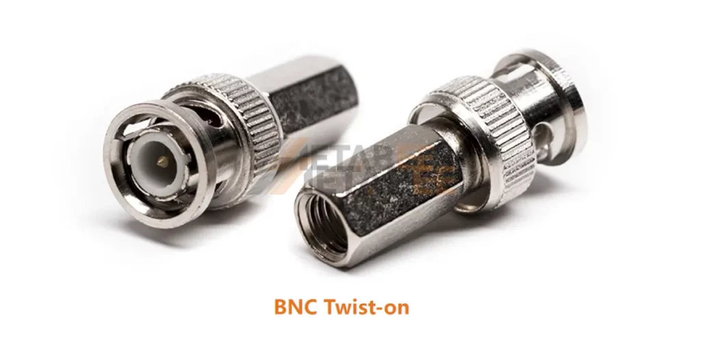
Disadvantages: Poor mechanical reliability. temporary connections, testing, and low-stress environments. Avoid in professional systems.
Panel Mount BNC Connector
Panel mount BNC connectors are installed directly onto equipment housings, control panels, or chassis structures.They provide a fixed interface for external cable connections.
Bulkhead BNC
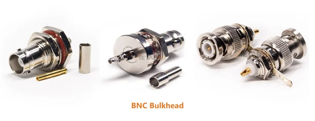
BNC bulkhead connectors feature an elongated threaded body with an integrated mounting flange, lock washer, and hex nut. Technicians mount them through a circular hole punched into an enclosure panel.
Key Features:
- Strong panel attachment
- Space-saving installation
- Improved cable management
PCB Mount BNC Connector
PCB mount BNC connectors are directly attached to printed circuit boards. This design reduces assembly complexity and minimizes additional RF transitions.
Three common PCB mount options include:
- Through Hole BNC Connector
- Edge Mount BNC Connector
- SMT BNC Connector
The correct type depends on PCB design, mechanical requirements, and signal frequency.
Through Hole BNC
Through-hole connectors feature rigid metal mounting legs and a center pin that extend through drilled PCB holes. Wave soldering or hand soldering secures the pins to the board. These connectors provide excellent mechanical anchor strength. They withstand repeated cable insertions without lifting copper pads off the circuit board.
Advantages:
- High mechanical strength
- Good resistance to repeated cable insertion
- Reliable solder joints
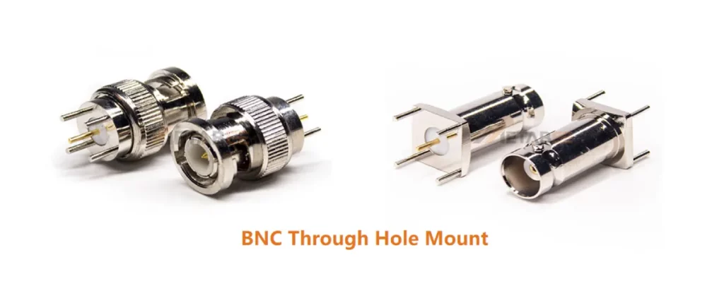
Through-hole connectors are suitable for applications where cables are frequently connected and disconnected.
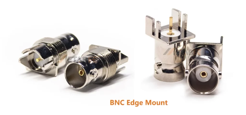
Edge Mount BNC
Edge mount (end-launch) BNC connectors slide directly onto the edge of a printed circuit board. The center contact aligns flush with the microstrip trace on the top layer.
Edge mount connectors reduce impedance discontinuities caused by vertical vias. They maintain signal integrity up to higher operating frequencies.
Advantages:
- Space-saving design
- Short signal path
- Reduced RF transmission loss
SMT BNC
Surface Mount Technology (SMT) places components directly onto PCB surface traces using solder paste and reflow processing. Designed with flat soldering pads, SMT BNC connectors support fully automated PCB assembly. During the process, automated pick-and-place machines position the connectors precisely onto the circuit board.
SMT connectors save board layer space and streamline automated assembly. However, they lack high mechanical shear strength. Designers often place mechanical hold-down posts alongside solder pads to handle connector stress.
Advantages:
- Compatibility with pick-and-place assembly
- Reduced PCB drilling requirements
- Compact board layouts
A BNC connector experiences significant insertion force during mating cycles. The PCB must provide enough support to prevent solder joint stress.
Types of BNC Connectors by Orientation
The connector orientation determines the cable exit direction after installation. BNC straight and right-angle connectors selection depends on available space and cable routing requirements.
Straight BNC Connector
Straight connectors have a linear connection structure. Engineers used straight connector in standard applications. This design provides simple installation and usually offers better mechanical strength.
Advantages:
- Simple mechanical structure
- Easy installation
- Low signal discontinuity
- High reliability
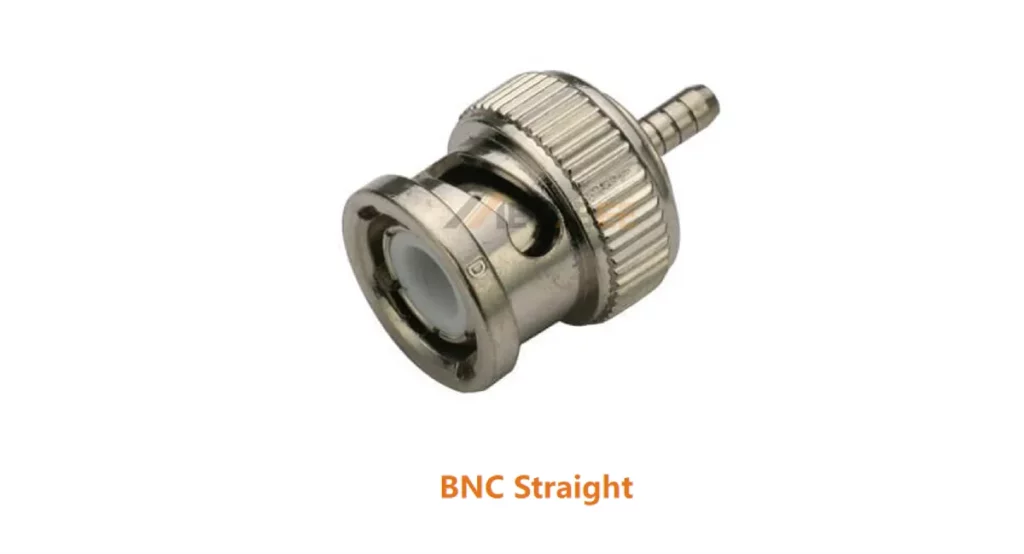
Straight connectors require more rear clearance because the cable exits directly from the equipment panel.
Right Angle BNC Connector
Right angle BNC connectors route the coaxial cable at a 90° angle relative to the mating interface. They are designed for applications with limited rear space.
Advantages:
- Reduced installation depth
- Better cable routing
- Lower mechanical stress on cable connections
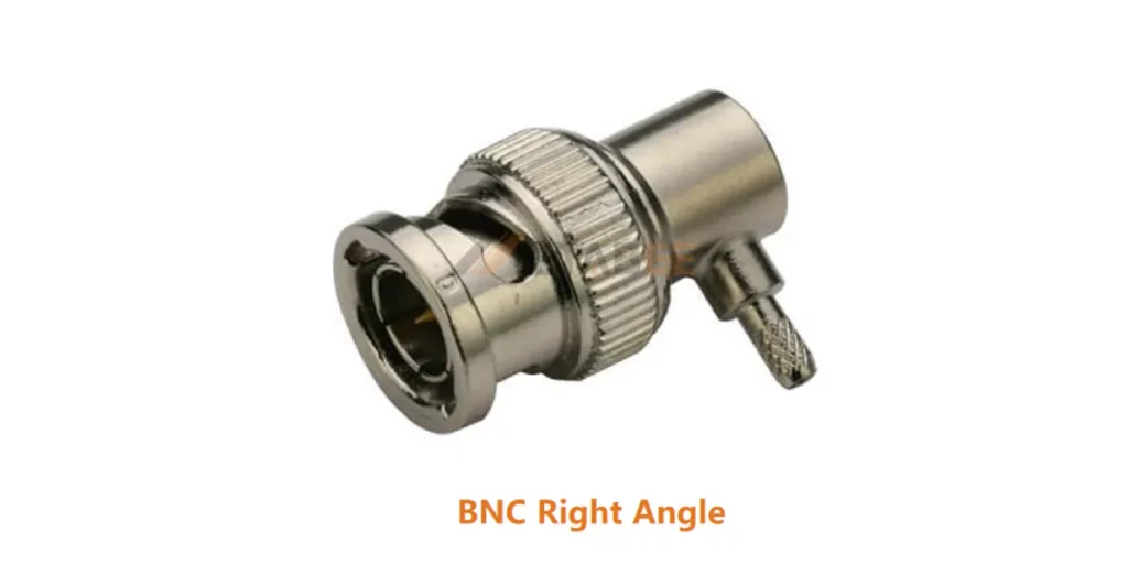
Engineers should check frequency ratings when using right-angle connectors in RF systems.
Other Specialized BNC Connector Types
Besides standard BNC connectors, several specialized versions exist for specific applications. These connectors maintain the basic BNC interface concept but modify size, performance, or mechanical structure.
Common specialized BNC types include: Mini BNC connectors, HD BNC connectors, Twin BNC connectors and SHV BNC connectors. Each type modifies the traditional BNC design for a specific purpose.
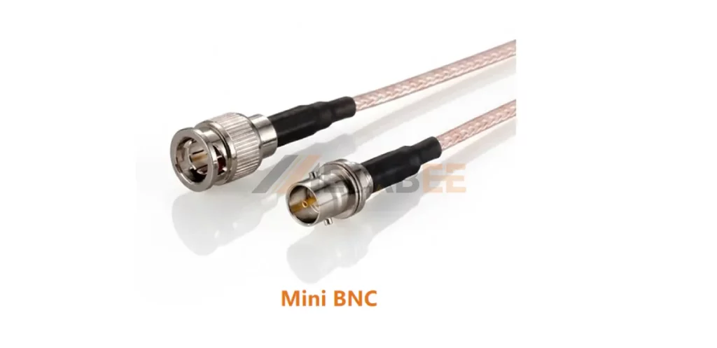
Mini BNC
Mini BNC connectors offer the same bayonet locking operation as standard BNCs in a 40% smaller footprint. Engineers must verify interface compatibility before replacement.
HD BNC
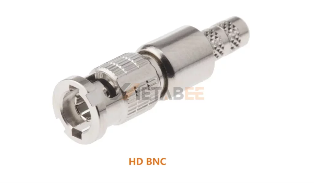
HD BNC connectors, also called High-Density BNC connectors, feature a compressed footprint 51% smaller than standard BNC connectors.
Engineers designed HD BNC specifically for 4K and 8K Ultra-HD video infrastructure. They support 12G-SDI protocol requirements with minimal return loss up to 12 GHz. They feature a traditional tactile bayonet lock mechanism.
Twin BNC
Twin BNC (Twinax) connectors combine two BNC interfaces into one bayonet housing. They provide two independent coaxial connections with a single mechanical structure. They terminate differential twinaxial cables with dual twisted central conductors. These connectors operate in low-frequency digital bus networks, military avionics systems, and balanced analog audio lines.
SHV BNC
SHV stands for Safe High Voltage. These connectors cater specifically to high-voltage laboratory applications. They include additional insulation and safety features to prevent accidental contact with high-voltage conductors.
Although they share a bayonet locking style, standard BNC and SHV connectors cannot mate mechanically. SHV connectors feature deeply recessed center conductors within heavy dielectric insulators.
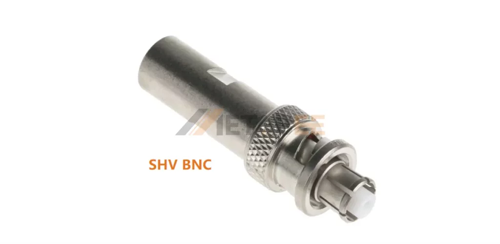
This design prevents electric shock if a user touches an energized, un-mated connector. SHV connectors safely handle up to 5,000 Volts DC at 5 Amperes.
BNC Connector Dimensions and Size
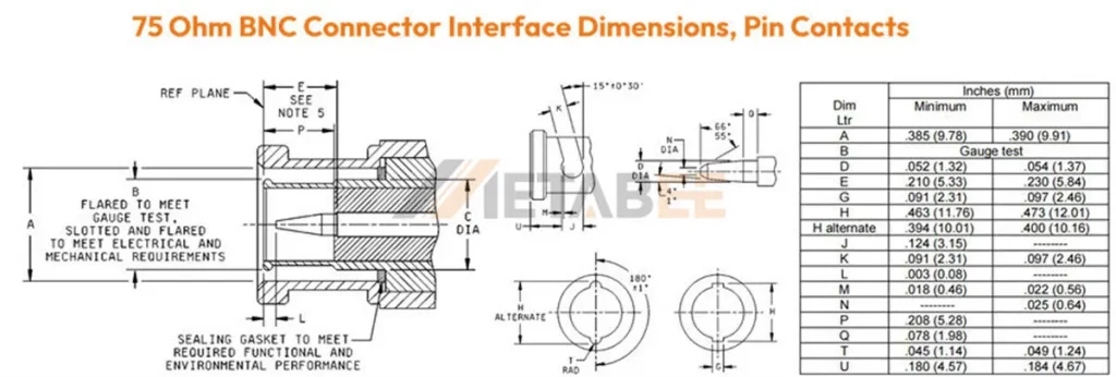
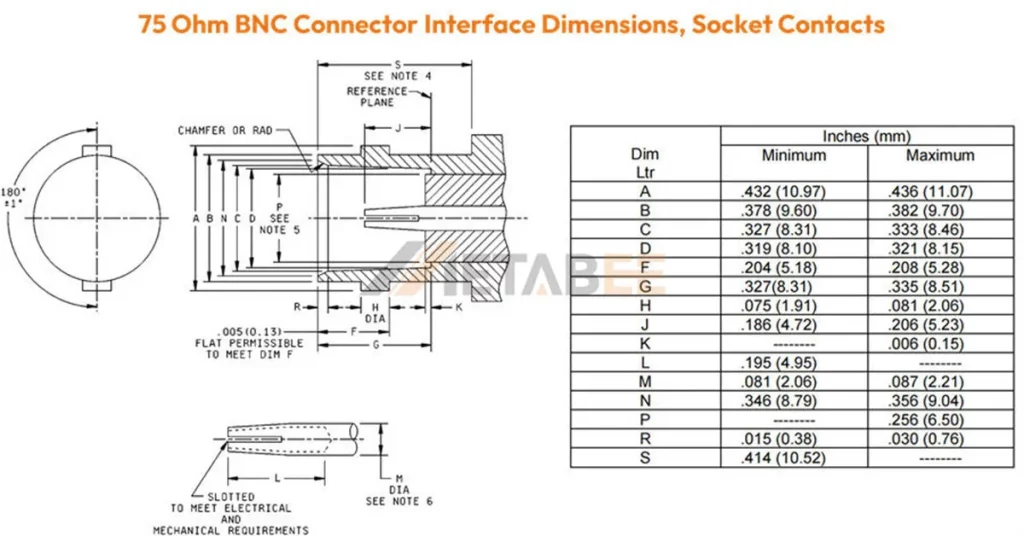
Dimensions of BNC connector are important factors when designing equipment interfaces, cable assemblies, and RF systems. BNC connectors are typically specified according to standards such as IEC 60169-8 and MIL-PRF-39012. These standards define key mechanical and electrical requirements for RF connectors.
Interface Dimensions of 50/75 Ohm BNC Male/Plug Connector
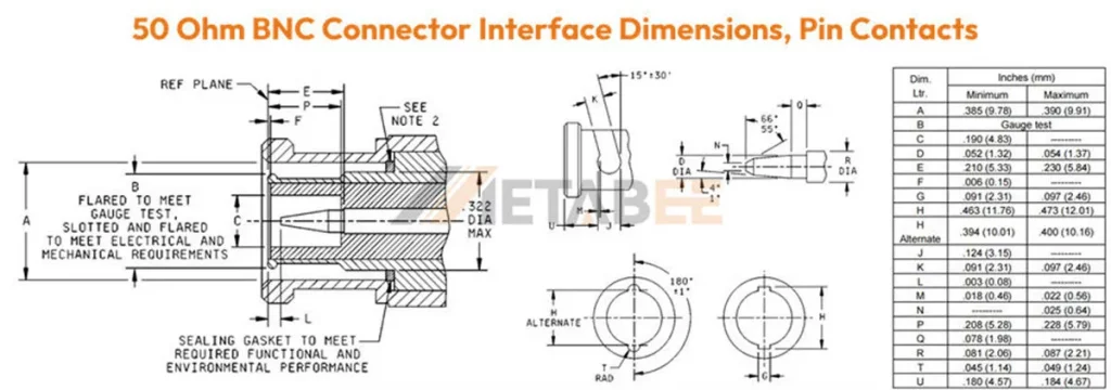
Interface Dimensions of 50/75 Ohm BNC Female/Socket Connector
Need a BNC Connector Drawing?
Need a product drawing or a customized BNC connector drawing for your application? Contact our technical team for drawings, specifications, and customization support.
How to Choose the Right BNC Connector Type
Selecting the suitable BNC connector type requires a comprehensive evaluation and consideration. Consider the following factors during the selection process:
Match the Impedance
The first consideration is impedance. BNC connectors are mainly available in 50-ohm and 75-ohm versions. 50-ohm BNC connectors are designed for RF and high-frequency applications. 75-ohm BNC connectors are commonly used in video and broadcast systems.
Consider Cable Compatibility
Match the connector rear termination barrel to your specific coaxial cable type. Common matching sets include:
- RG-58 / RG-142 / LMR-195: Requires standard 50 Ohm BNC crimp barrels.
- RG-59 / RG-6 / Belden 1694A: Requires precise 75 Ohm video crimp or compression connectors.
- RG-174 / RG-316: Requires miniature sub-flexible coaxial crimp ferrules.
Select the Mounting Configuration
Select cable mount BNCs (crimp, solder, or compression) for cable assemblies, or panel mount versions to relieve stress on internal circuits at equipment interfaces. For circuit boards, choose through-hole BNCs for superior mechanical strength or SMT versions to enable automated assembly.
Evaluate Electrical Performance
Evaluating a BNC connector requires checking its frequency range, insertion loss, and return loss to ensure low signal reflection and consistent transmission performance. Additionally, engineers must also confirm the voltage rating, switching to SHV connectors when operating under high-voltage conditions.
Consider Environmental Conditions
Indoor laboratory settings allow standard nickel-plated brass connectors. Outdoor marine setups require gold-plated contacts, stainless steel bodies, and internal dual O-ring IP67 seals.
Metabee provides various BNC connectors and our engineering team can help you select suitable connectors .
If you are unsure which BNC connector type is suitable for your application or need support with a specific RF design, contact us for technical support and product selection assistance.
Conclusion
BNC connectors are available in various types and configurations to support different signal transmission requirements. From standard 50 Ohm and 75 Ohm BNC connectors to specialized options such as HD BNC and SHV BNC connectors, each type is designed for specific applications.
Choosing the right BNC connector requires evaluating factors such as impedance, cable compatibility, mounting method, termination style, and operating environment. These considerations help maintain signal integrity and ensure reliable connections.
For custom BNC connector requirements, including specific dimensions, cable assemblies, mounting configurations, or electrical specifications, contact us today for professional support and customized solutions.
Related Products
- BNC Connectors
- BNC Male
- BNC Female
- 50 Ohm BNC
- 75 Ohm BNC
- Right Angle BNC
- Panel Mount BNC
- Bulkhead BNC
- PCB Mount BNC
- Solder BNC
- Crimp BNC
- Compression BNC
FAQ
Q1: What is a BNC connector?
A: BNC connectors are quick-connect RF coaxial connectors that uses a bayonet locking mechanism for fast mating and secure connection. They are used in oscilloscopes, signal generators, RF test equipment, surveillance cameras, broadcast video systems, antennas, and industrial measurement equipment.
Q2: What are the different types of BNC connectors?
A: The most common categories include:
- By gender and polarity : BNC male, BNC female, RP-BNC male and RP-BNC female
- By impedance: 50 ohm BNC and 75 ohm BNC
- By mounting method: cable type BNC, panel mount BNC, and PCB mount BNC
- By orientation: straight BNC and right-angle BNC
- By application: mini BNC, HD BNC, twin BNC, and SHV BNC
Q3: What is the difference between 50-ohm and 75-ohm BNC connectors?
A: The main difference is characteristic impedance.
- 50-ohm BNC connectors are mainly used in RF and measurement systems.
- 75-ohm BNC connectors are commonly used in video and broadcast applications.
Q4: What is the main structural difference between BNC and TNC connectors?
A: BNC connectors use a bayonet quick-twist locking system. TNC connectors use a threaded coupling mechanism that provides superior stability under high vibration conditions.
Q5: Can a 50-ohm BNC connector connect to a 75-ohm BNC connector?
A: Physically, many 50-ohm and 75-ohm BNC connectors can mate.
However, they have different internal structures. Mixing them may cause impedance mismatch and signal reflection. For precision RF or high-frequency applications, engineers should use matching impedance components.
Q6: What is a reverse polarity BNC connector (RP-BNC)?
A: It has the reversed center contact arrangement compared with a standard BNC connector. The RP-BNC male plug contains a center socket, while the RP-BNC female jack contains a center pin. The purpose of RP-BNC designs is usually to prevent accidental connection with standard BNC interfaces in specific applications.
