
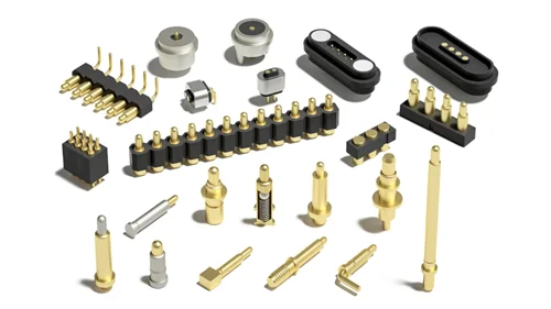
Micro-D connectors provide high-density electrical interconnections in systems with strict space, weight, and reliability requirements. Engineers commonly use them in aerospace electronics, military equipment, satellite systems, and compact industrial devices. Two important references in this field are MIL-DTL-83513 and China’s J30J connector family. Both relate to compact rectangular connectors, but their specifications, qualification systems, and product implementations may differ.
This guide explains the differences between Micro-D connectors, MIL-DTL-83513, and J30J. It also covers pinouts, connector configurations, technical specifications, applications, and practical selection criteria.
- Micro-D Connectors: J30J and MIL-DTL-83513 Explained
- Contact Arrangements & Pinouts
- Types and Configurations
- Key Specifications
- Applications of Micro-D Connectors
- Comparison: Standard D-Sub vs. Micro-D vs. Nano-D
- How to Choose the Right Micro-D Connector (MIL-DTL-83513 / J30J)
- Conclusion
- Related Products
- FAQ
Micro-D Connectors: J30J and MIL-DTL-83513 Explained
What Are Micro-D Connectors?
Micro-D connectors are high-density, polarized D-shaped interconnects with a contact pitch of 0.050 inches (1.27 mm). They provide one of the highest contact densities available in a rugged metal shell. Common contact counts include 9, 15, 21, 25, 31, 37, and 51 positions. Availability varies by manufacturer, connector series, and applicable specification. These connectors feature the twist-pin contact system design.
To standardize their design, performance, and qualification requirements, many Micro-D connectors are manufactured in accordance with MIL-DTL-83513. This specification provides a common technical basis for specifying and evaluating compatible families of microminiature rectangular connectors. Its purpose is to help engineers select connectors against defined mechanical and electrical requirements. It also provides a basis for qualification and procurement in applications with documented reliability requirements.
What Are J30J Connectors?
J30J connectors are chinese miniature rectangular connectors designed for compact, high-density interconnections. J30J products conform to the Chinese military standard GJB 2446A. They match MIL-DTL-83513 in contact centerlines, overall outer envelope dimensions, and basic shell materials.
Common J30J contact arrangements include 9, 15, 21, 25, 31, 37, 51, 66, 69, 74, 100, and 144 contacts. Domestic Chinese aerospace, radar, unmanned vehicle, and ground defense platforms use J30J as their default micro-miniature rectangular connector.
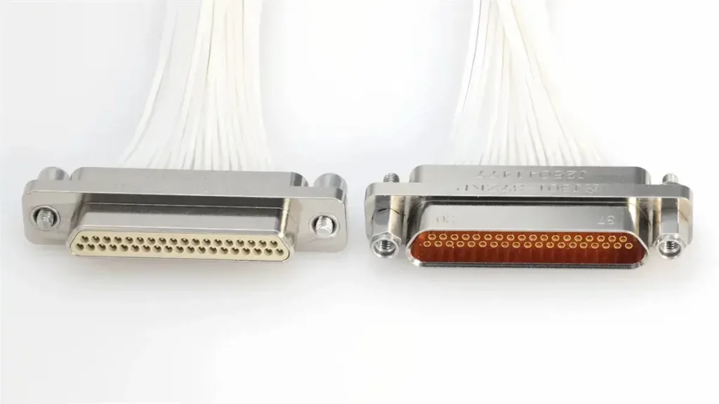
How to specify Metabee J30J Series Numbers
What Is MIL-DTL-83513?
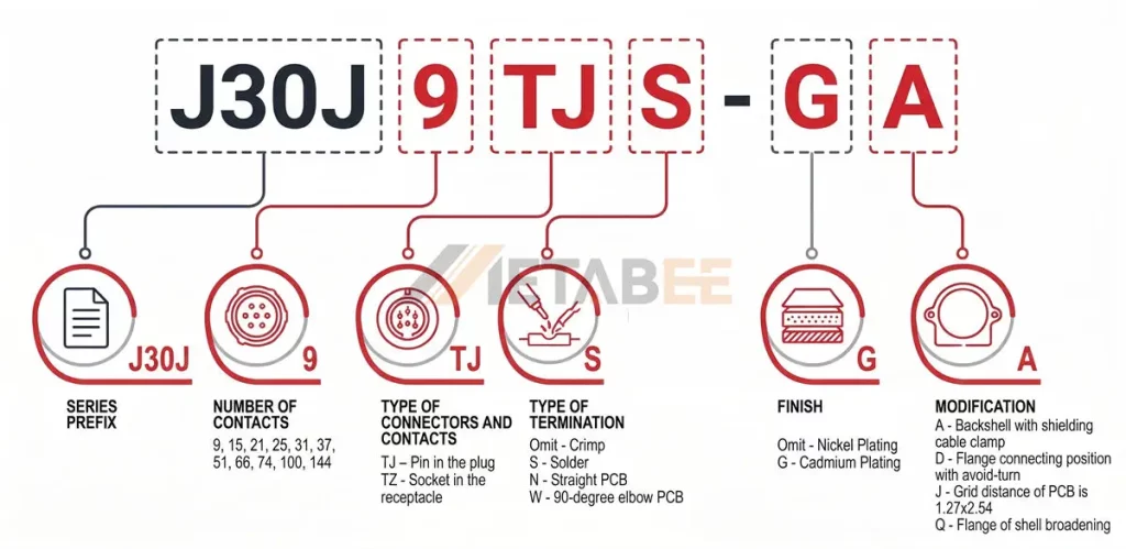
MIL-DTL-83513 is a United States military detail specification covering miniature rectangular electrical connectors commonly associated with micro-D designs. It defines requirements for applicable connector configurations, performance, testing, and qualification.
How to Read MIL-DTL-83513 Part Numbers
MIL-DTL-83513 connector part numbers use the M83513 designation, followed by a slash-sheet number and additional configuration codes. Their structure depends on the applicable slash sheet and manufacturer coding system.
In commonly used product catalogs, /01 identifies a metal-shell solder-cup plug configuration, while /02 identifies its receptacle counterpart.
Military part numbers follow a structured syntax: M83513/XX-XXXX.
Consider the illustrative part number M83513/01-AN.
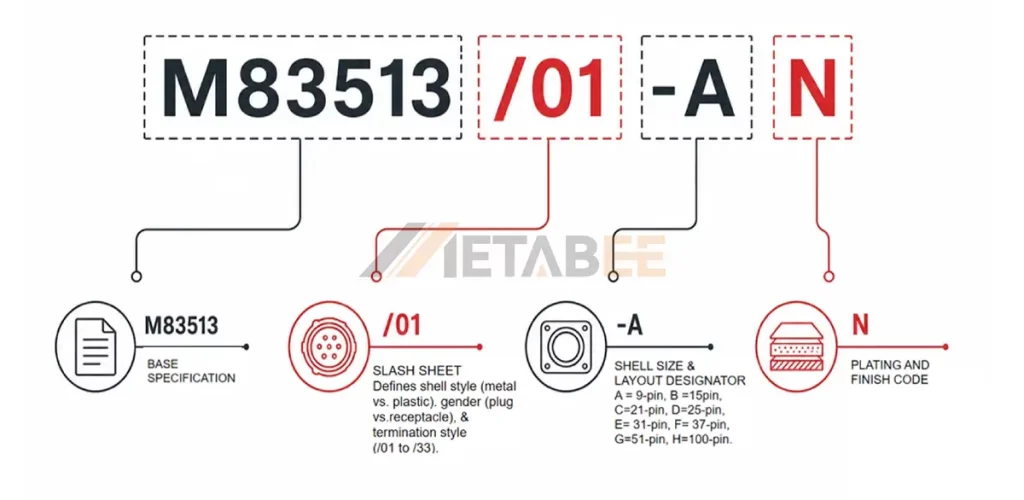
Key elements include:
- Slash Sheet (/01 to /33): Defines shell style (metal vs. plastic), gender (plug vs. receptacle), and termination style (solder cup, pre-wired pigtail, or PCB footprint).
- Shell Size Letter: A (9-pin), B (15-pin), C (21-pin), D (25-pin), E (31-pin), F (37-pin), G (51-pin), H (100-pin).
MIL-DTL-83513 Compliance and Qualification
Compliance and qualification determine whether a connector meets the requirements specified for a particular application or procurement contract.
Compliance with MIL-DTL-83513 requires verifying the manufacturer’s qualification status, the exact part-number configuration, and supporting technical and quality documentation. Key records include applicable specifications, drawings, qualification records, test reports, material and finish details, traceability records, and certificates of conformity. A certificate alone does not prove qualification, and qualified connectors may still require application-level testing. For aerospace and defense projects, approved-source requirements and substitution restrictions must be confirmed before procurement.
Need Help Verifying MIL-DTL-83513 Requirements?
Contact our technical team to discuss the applicable specification, qualification requirements, and supporting documentation for your Micro-D connector application.
MIL-DTL-83513 vs. J30J (GJB 2446A): locking Threads
MIL-DTL-83513 and J30J share similar connector concepts, but they belong to different specification systems. The primary practical difference is the locking screw thread: standard J30J connectors commonly use metric M2 threads, whereas MIL-DTL-83513 connectors typically use imperial 2-56 UNC threads.
Quick Comparison Table:
| Feature | MIL-DTL-83513 | J30J |
| Standard | U.S. military specification | Chinese GJB 2446 specification |
| locking Threads | Imperial (2-56 UNC, 4-40 UNC) | Metric (M2, M2.5) |
| Contact Type | Twist Pin | Twist Pin |
| Contact Pitch | 0.050″ (1.27 mm) | 0.050″ (1.27 mm) |
| Contact Arrangements | Defined by applicable specification sheets | Varies by J30J specification and manufacturer |
| Shell Material | Aluminum alloy, Stainless Steel | Aluminum alloy, Stainless Steel |
| Common Finishes | Nickel, Cadmium | Nickel, Cadmium |
Important: This table provides a general framework, not a formal cross-standard equivalence determination.
MIL-DTL-83513 and J30J Cross-Reference Table
A cross-reference table helps engineers shortlist potential alternatives between MIL-DTL-83513 Micro-D products and J30J connectors.
The following table provides a preliminary family-level comparison. It does not authorize direct substitution between individual part numbers.
| Pin Count | MIL-DTL-83513 Shell Code | J30J Equivalent Layout | Rows | Typical Shell Width (Plug, mm) |
| 9 | A | J30J-9 | 2 | ~19.8 mm |
| 15 | B | J30J-15 | 2 | ~23.6 mm |
| 21 | C | J30J-21 | 2 | ~27.4 mm |
| 25 | D | J30J-25 | 2 | ~30.0 mm |
| 31 | E | J30J-31 | 2 | ~33.8 mm |
| 37 | F | J30J-37 | 2 | ~37.6 mm |
| 51 | G | J30J-51 | 2 | ~36.3 mm |
| 100 | H | J30J-100 | 4 | ~55.0 mm |
Important: The table identifies contact-count candidates, not approved mating pairs. The existence of the same contact count does not prove identical dimensions or pin assignments.
Explore Metabee’s J30J Micro-D Connectors Catalog
Looking for reliable J30J Micro-D connectors for your application? Explore Metabee’s J30J connector catalog to discover available models, contact arrangements, configurations, and technical specifications.
Whether you need standard J30J connectors or customized solutions, contact our team for product details, technical support, and quotations.
[Download the J30J Micro-D Connectors Catalog]
Compatibility and Interchangeability Considerations
Connector compatibility requires verifying mechanical dimensions, mounting interfaces, contact assignments, electrical performance, environmental requirements, and qualification status. Even connectors with identical contact counts may differ in pinout or performance. Cross-reference listings alone cannot guarantee interchangeability; manufacturer confirmation and appropriate fit and electrical testing are recommended.
Need a Compatible Micro-D Connector Replacement?
Share your existing part number, connector drawing, or technical specifications with our team. We can help assess dimensional and electrical compatibility and identify potential replacement options for your application.
Contact Arrangements & Pinouts
Common Micro-D Contact Arrangements
The manufacturer’s drawing determines the contact numbering arrangement. The system schematic or wiring diagram determines whether each contact carries power, ground, a differential signal, or another circuit function.
Common MIL-DTL-83513 Micro-D arrangements include 9, 15, 21, 25, 31, 37, 51, and 100 contacts. J30J product catalogs may also list 66-, 69-, 74-, or 144-contact arrangements.
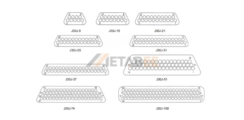
Micro-D Connector Pinouts
Micro-D connector pinouts describe the physical positions and numbering of electrical contacts. They do not automatically define the circuit function assigned to each contact.
Illustrative 25-Position Pin Assignment
The following table shows a hypothetical 25-contact signal assignment. It illustrates circuit allocation only and does not represent a universal MIL-DTL-83513 or J30J pinout.
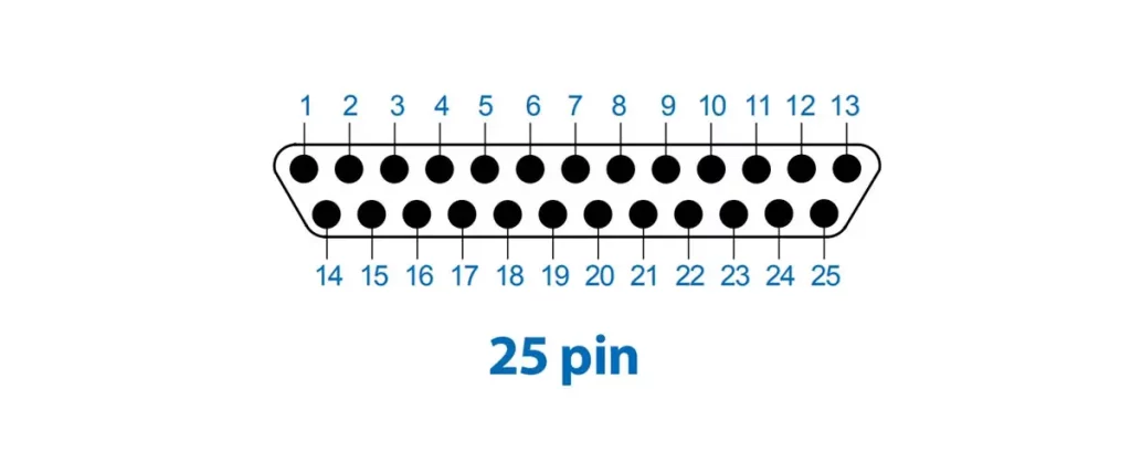
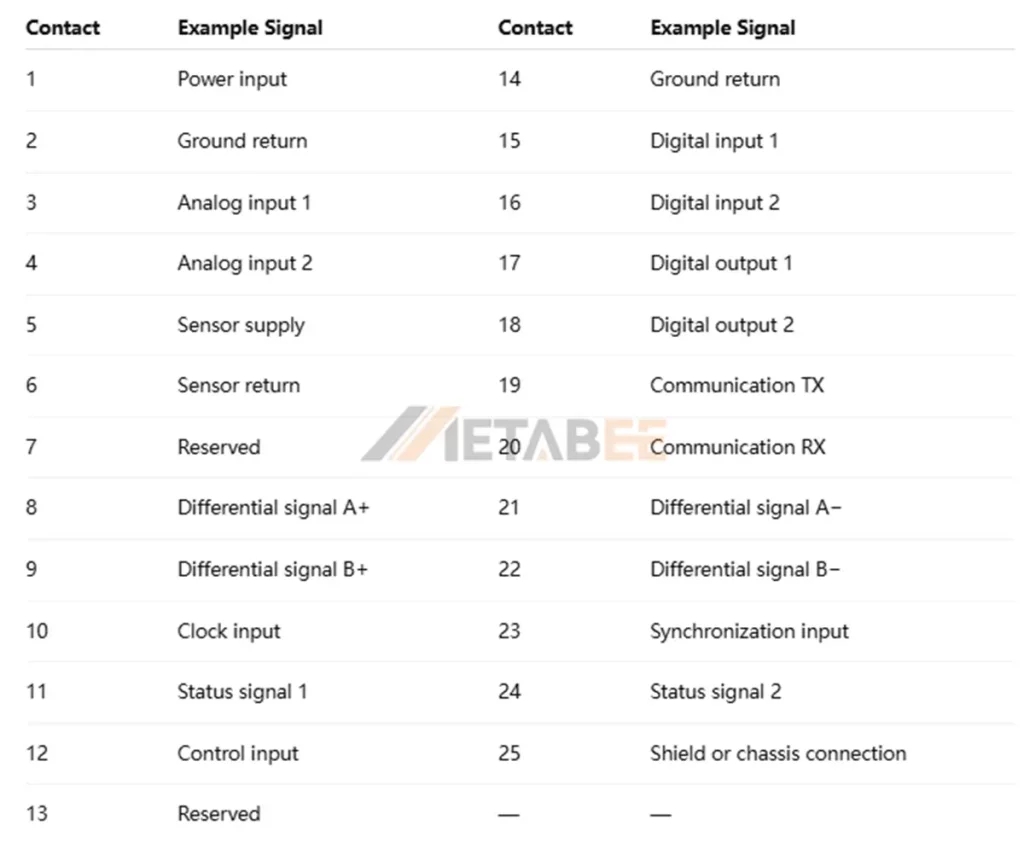
The table demonstrates one possible allocation, not a universal wiring scheme. Actual assignments must follow the system schematic and controlled interface documentation.
Need a Custom Micro-D Pinout or Contact Arrangement?
If your application requires a specific pin assignment, contact configuration, or wiring layout, contact our engineering team to discuss your design requirements and available customization options.
Types and Configurations
J30J Micro-D connectors are available in multiple termination and mounting configurations. Selecting the correct configuration helps control assembly complexity, installation space, and long-term serviceability.
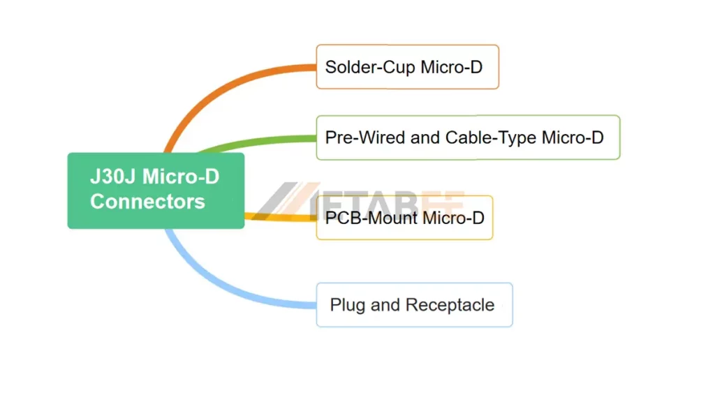
- Solder-Cup Micro-D Connectors
Solder-cup variants provide individual hollow solder cups at the rear of each contact. They allow field wiring, custom wire colors, and small harness runs.
- PCB-Mount Micro-D Connectors
PCB-mount Micro-D connectors connect directly to printed circuit boards. Common terminal configurations include through-hole and surface-mount designs, depending on the product family.
- Pre-Wired and Cable-Type Micro-D Connectors
Because hand-soldering dense connectors is risky, many production programs buy pre-wired assemblies.
- Plug and Receptacle Configurations
Micro-D terminology defines the “plug” as the connector carrying the male pin contacts, while the “receptacle” holds the female socket contacts. Micro-D plugs have an outer shroud that fits inside the receptacle shell. Metal shells provide full 360-degree shielding against electromagnetic interference (EMI).
Key Specifications
The values below are selection criteria rather than universal micro-D ratings. Engineers must obtain the actual limits from the applicable specification sheet and manufacturer documentation.
| Operating Temperature | 55℃ to +125℃ |
| Rated Current | 3A |
| Humidity | 98% at +40℃ |
| Insulation resistance | ≥5000Mn |
| Contact resistance | s10mn |
| Durability | 500 times |
| Dielectric Strength | 800 V |
| Vibration | 10Hz ~ 2000Hz 196 m/s2 |
| Random Vibration | 10Hz-2000Hz 196 m/s2Power density 0.4G2/Hz. The total acceleration-root-mean square is 23.1G |
| Shock | 735 m/s2 , 11ms |
| Acceleration | 735 m/s2 |
| Low air pressure | 4.5 kPa 200V |
Applications of Micro-D Connectors
Micro-D connectors suit compact electrical interfaces that require relatively high contact density and reliable mechanical connections.

- Aerospace and Avionics: Avionics, airborne computing systems, and high-density signal interconnects.
- Military and Defense: Military electronic equipment, communication systems, and control equipment.
- Industrial Automation: Compact control equipment, industrial electronic systems, and high-density signal connectivity.
- Medical and Scientific Equipment: High-density electronic instruments, testing equipment, and scientific apparatus.
Comparison: Standard D-Sub vs. Micro-D vs. Nano-D
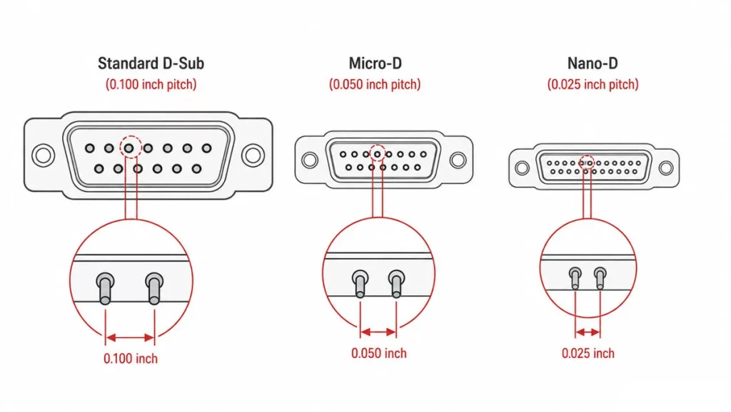
Standard D-Sub, Micro-D, and Nano-D connectors share a general rectangular connector concept. However, their dimensions, contact spacing, and intended packaging requirements differ. The principal distinction is the balance between connector size, contact density, handling, and application requirements.
- Standard D-Sub Connectors
Standard D-Sub connectors are electrical connectors featuring a D-shaped metal shell and multiple contacts arranged in standardized configurations. They are widely used for data transmission, signal connections, and industrial control. Common configurations include DE-9, DB-15, and DB-25. The shell provides mechanical protection and helps prevent incorrect mating.
- Micro-D Connectors
Micro-D connectors are miniature rectangular connectors developed for applications where conventional D-Sub connectors occupy too much space or add excessive weight. They retain the general D-shaped mating concept while reducing contact spacing and overall package dimensions.
- Nano-D connectors
Nano-D connectors provide an even smaller interface than conventional Micro-D connectors. MIL-DTL-32139 specifies nanominiature connectors with 0.025-inch (0.64 mm) spacing between contacts in the same row.
Contact pitch is the center-to-center distance between adjacent contacts. It is one of the most useful parameters for distinguishing Standard D-Sub, Micro-D, and Nano-D connectors.
Quick Comparison Table
| Feature | Standard D-Sub | Micro-D | Nano-D |
| Applicable Military Specification | MIL-DTL-24308 | MIL-DTL-83513 | MIL-DTL-32139 |
| Contact Pitch | 2.77 mm (0.100 in) | 1.27 mm (0.050 in) | 0.635 mm (0.025 in) |
| Size | Standard | Miniature | Ultra-miniature |
| Contact Density | Moderate | High | Very high |
| Contact Count | Commonly 9–50 positions | Commonly 9–51 positions | Commonly 9–51 positions |
| Space Efficiency | Moderate | High | Very high |
| Weight | Highest | Lower | Lowest |
| Applications | Industrial equipment, computers, instrumentation | Aerospace, military electronics, avionics | Satellites, space electronics, miniature avionics |
| Main Limitation | Larger footprint | Smaller contacts require careful assembly | Tight dimensions and demanding assembly requirements |
How to Choose the Right Micro-D Connector (MIL-DTL-83513 / J30J)
Selecting a Micro-D connector requires a structured review of electrical, mechanical, environmental, and procurement requirements. The following process helps engineers and professional buyers narrow the available configurations.
Step 1 Define electrical requirements
Start by documenting the required current, operating voltage, signal frequency, insulation requirements, and grounding arrangement. Include any differential pairs, sensitive analog signals, or high-speed communication channels. Check the manufacturer’s current ratings and derating guidance.
For high-speed signals, evaluate impedance, crosstalk, shielding, and the complete transmission path. Connector selection must account for cable and PCB characteristics as well as contact geometry.
Step 2 Determine contact count and connector configuration
Calculate the number of required circuits, including signal, ground, and spare contacts. Then identify the required plug or receptacle configuration. Confirm contact gender, mating orientation, shell dimensions, and polarization features.
Use the applicable contact-arrangement drawing to verify numbering. Never infer pin assignments from the contact count alone.
Step 3 Confirm mounting and termination requirements.
Match the termination style to your manufacturing capabilities:
- Use pre-wired pigtails for rapid harness assembly and consistent strain relief.
- Choose straight or right-angle PCB leads for rigid backplanes.
- Avoid solder-cup terminations for large production batches. Hand-soldering 0.050-inch pins slows down assembly lines and raises defect risks.
Step 4 Evaluate environmental and mechanical conditions
Identify the connector’s expected temperature range, vibration exposure, shock loads, humidity, contamination, and corrosion risks. Assess cable movement and mounting stiffness as well. For aerospace and defense equipment, review the relevant environmental qualification requirements. Confirm that the complete assembly meets the intended operating conditions.
Step 5 Verify MIL-DTL-83513 compliance and qualification requirements
Determine whether the project requires a qualified MIL-DTL-83513 product or permits a commercially supplied connector that meets the necessary technical requirements.
- For qualified applications, check the applicable QPL entry and exact part number. Confirm that the supplier’s documentation matches the purchase specification.
- For J30J applications, confirm the applicable GJB 2446A requirements and any additional product-specific standards.
Step 6 Compare manufacturer drawings and part numbers
Obtain complete drawings for the selected connector and its mating component. Check the complete part numbers rather than comparing only their contact counts. For cross-reference projects, document the engineering basis for the proposed replacement.
Step 7 Evaluate customization and cable assembly options
Some projects need special wire lengths, shielding arrangements, mounting hardware, or modified termination configurations. Review available standard options before requesting a custom part. For custom assemblies, define the pinout, wire type, shielding method, cable length, and inspection requirements.
Need Help Selecting the Right Micro-D Connector?
Share your required contact count, mounting style, termination method, electrical specifications, environmental conditions, and qualification requirements. Our technical team can help evaluate suitable connector options and discuss customization possibilities.
Request a Quote Today to discuss your project requirements and find the right Micro-D connector solution.
Conclusion
Micro-D connectors bridge the gap between high-power, bulky legacy connectors and fragile sub-miniature designs. Their twist-pin architecture delivers reliable contact retention. MIL-DTL-83513 defines requirements for applicable micro-miniature rectangular connectors. J30J products associated with GJB 2446A serve a related connector category.
Engineers should verify contact arrangements, mechanical dimensions, termination methods, electrical ratings, environmental performance, and qualification status before selecting or substituting a connector. For procurement and engineering changes, use manufacturer drawings and applicable standards as the primary references.
Find the Right Micro-D Connector for Your Project?
Whether you need a standard Micro-D connector, a MIL-DTL-83513 solution, a J30J-compatible option, or a custom cable assembly, our team is ready to discuss your requirements.
Contact us today for product information, technical support, customization options, or a project-specific quotation.
Related Products
FAQ
Q1:What is a Micro-D connector?
A: A Micro-D connector is a micro-miniature rectangular electrical connector designed for high contact density and compact installation. It use 1.27 mm contact pitch and twisted-pin contact technology.
Q2:What is MIL-DTL-83513?
A: MIL-DTL-83513 is a United States military detail specification covering polarized-shell, micro–miniature rectangular electrical connectors. The applicable specification sheet defines requirements for the selected connector configuration.
Q3:What is a J30J connector?
A: J30J is a connector series associated with Chinese micro-miniature rectangular connectors. These products are commonly associated with GJB 2446A and may have additional manufacturer-specific requirements.
Q4:What is the standard contact pitch of a Micro-D connector?
A: Conventional Micro-D connectors commonly use a 0.050-inch (1.27 mm) contact pitch. Actual dimensions and contact layouts depend on the specified connector design.
Q5:How many contacts can a Micro-D connector accommodate?
A: Micro-D connectors are available in multiple contact counts, depending on the product family. Common configurations include 9, 15, 21, 25, 31, 37, 51, and 100 contacts in certain series.
Q6:Are MIL-DTL-83513 and J30J connectors interchangeable?
A: No. Engineers must compare mating dimensions, contact arrangements, mounting interfaces, electrical ratings, environmental performance, and qualification requirements before approving a substitution.
Q7:Are All Micro-D Connectors MIL-DTL-83513 Qualified?
A: No. Not all Micro-D connectors are qualified to MIL-DTL-83513. Some commercial off-the-shelf (COTS) products are not listed on the Defense Logistics Agency’s Qualified Products List (QPL).
Q8:What should you verify before replacing an M83513 connector with a J30J connector?
A: Compare the exact part numbers, mating-face dimensions, contact numbering, mounting-hole positions, electrical ratings, environmental requirements, and qualification documentation. Obtain engineering approval before making a controlled substitution.
Q9:What materials are used in Micro-D connector shells?
A: Micro-D connector shells use aluminum alloys, stainless steel. Material selection affects weight, mechanical strength, corrosion resistance, and electromagnetic shielding.
