
You need reliable connections when sourcing components for high-frequency RF systems, broadcast networks, or precision instrumentation. The BNC (Bayonet Neill–Concelman) connector remains a staple in these industries. Engineers love its quick bayonet locking mechanism and robust performance. However, not all BNC connectors deliver the same quality.
At Metabee, we understand that judging a connector by its external appearance is a dangerous gamble. The true metric of a connector’s quality lies beneath its metallic shell. You can only prove this quality through rigorous, factory-level electrical testing. A visually perfect connector can harbor microscopic defects. These hidden flaws easily lead to catastrophic signal loss or hardware damage.
This comprehensive guide delves into why factories must rigorously test manufactured BNC connectors. We will explore the core electrical parameters that define connector quality. We will also break down the step-by-step processes and equipment experts use to evaluate Voltage Standing Wave Ratio (VSWR), contact resistance, and insulation integrity.
What is a BNC Connector?
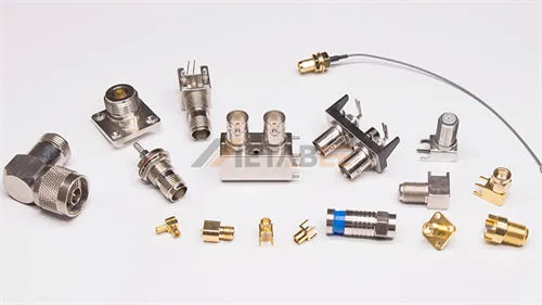
The BNC (Bayonet Neill–Concelman) connector is a miniature, quick-connect RF connector. Engineers use it primarily for coaxial cable terminations. It features a unique slotted bayonet locking mechanism. This brilliant design allows operators to connect and disconnect cables rapidly with a simple quarter-turn.
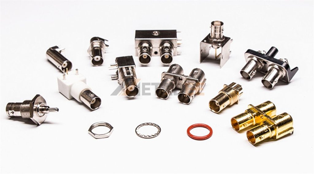
You will typically find BNC connectors in two standard characteristic impedances: 50 Ohm and 75 Ohm. The 50-ohm connectors dominate general RF applications and standard test instruments. Meanwhile, 75-ohm versions excel in broadcast video and high-definition television (HDTV) environments. At Metabee, we manufacture both types to support diverse industrial and commercial applications.
Why Factories Must Test Manufactured BNC Connectors
Consistency is just as important as peak performance in electronic components. Factories produce BNC connectors and coaxial cable assemblies on mass scales. They machine brass bodies, inject PTFE (Teflon) dielectrics, and plate delicate center pins with gold.
Manufacturing variances remain inevitable despite advanced CNC machining and automated assembly lines. Why is post-production factory testing an absolute non-negotiable step?
Catching Assembly and Material Variances
A BNC connector relies on exact geometric dimensions. These dimensions maintain its characteristic impedance. A micrometer deviation in the center pin diameter or dielectric thickness drastically alters electrical properties.

Furthermore, testing identifies plating defects. A thin or uneven gold plating on the center contact oxidizes rapidly. This oxidation leads to poor conductivity over time. Factory-level testing catches these invisible variances before the batch leaves the facility.
Validating the Crimping and Soldering Process
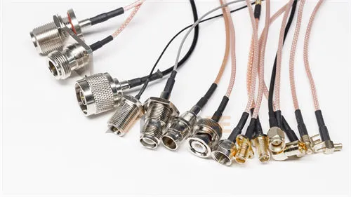
Technicians rarely use BNC connectors in isolation. They terminate them onto coaxial cables. The termination process always introduces some risk of human or mechanical error. Workers might crimp the outer ferrule or solder the center pin imperfectly.
A poorly executed crimp might hold physically but fail electrically. This failure introduces severe impedance mismatches. Comprehensive electrical testing verifies the integrity of the entire cable assembly, not just the raw connector.
Mitigating Risk
Field failures are incredibly costly for Original Equipment Manufacturers (OEMs). A failing $2 connector can bring down a $20,000 medical imaging device or military communication array.
Premium manufacturers like Metabee implement stringent factory testing to mitigate this risk. We provide our customers with documented peace of mind. This strict quality control significantly reduces field failure rates and warranty claims.
Core Electrical Parameters to Evaluate
Testing facilities focus on three critical electrical parameters to guarantee signal integrity and safety. Any engineer evaluating a BNC connector test report must understand these metrics.
VSWR (Voltage Standing Wave Ratio)
You want 100% of the signal power to travel from the source to the load during RF transmission. However, any impedance mismatch within the connector causes signal reflection. VSWR measures this reflection back toward the source.
A VSWR of 1.0:1 implies a perfect match with zero reflection. In the real world, a lower VSWR means better power transfer efficiency. It also means less signal distortion, preventing video ghosting or data packet loss. High-quality BNC connectors must maintain a consistently low VSWR across a broad frequency range.
Contact Resistance
Contact resistance measures the electrical resistance at the mating points of the connector. Testers measure this in two places for a BNC connector:
- Center Conductor Resistance: The resistance between the male pin and the female socket.
- Outer Conductor (Shield) Resistance: The resistance between the bayonet locking bodies.
These values must stay incredibly low, measured in milliohms (mΩ). High contact resistance leads to signal attenuation. It also causes dangerous heat generation in power-transmitting applications.
Insulation Resistance and Dielectric Withstanding Voltage (Hipot)
A dielectric insulator, usually PTFE, separates the center conductor and the outer shield. Insulation resistance measures the electrical resistance of this dielectric. This ensures no current leaks between the core and the shield.
Engineers test Dielectric Withstanding Voltage using a “Hipot” (High Potential) test. They apply a massive voltage spike to the connector. They do this to see if the dielectric breaks down or arcs. This test ensures the connector can handle voltage surges safely.
Summary Table of Key Parameters
Here is a quick reference guide summarizing the core parameters, their significance, and the standard acceptable values for high-quality BNC connectors:
| Parameter | Meaning & Importance | Standard / Acceptable Value |
| VSWR | Measures signal reflection caused by impedance mismatch. Lower values guarantee better RF power transfer and less distortion. | ≤ 1.6 (across tested frequency, e.g., DC to 6.0 GHz) |
| Contact Resistance (Center) | Electrical resistance at the inner pin connection. Low resistance prevents signal attenuation and dangerous heating. | ≤ 15 mΩ |
| Contact Resistance (Outer) | Electrical resistance at the outer bayonet/shield connection. Ensures proper grounding and shielding integrity. | ≤ 10 mΩ |
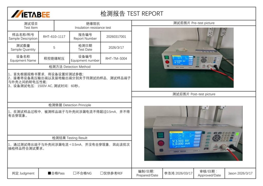
| Hipot (Dielectric Withstand) | Tests the PTFE dielectric’s ability to withstand massive voltage surges without arcing or failing. | 1500V AC for 60 seconds; Leakage < 0.5 mA |
How to Test BNC Connectors: Processes and Equipment
Reviewing a factory test report provides invaluable insights into a manufacturer’s quality assurance capabilities. Here is the detailed breakdown of how operators execute these three core tests on the factory floor.
Test 1: VSWR Testing Process
Equipment Required: Vector Network Analyzer (VNA) and high-precision calibration kits.
The Process:
- Calibration: Technicians must first rigorously calibrate the VNA to the specific frequency range. This calibration removes the electrical effects of the test cables.
- Connection: Next, testers attach the BNC connector or terminated cable assembly to the VNA test ports.
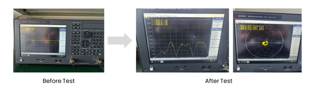
- Frequency Sweep: The VNA sends RF signals through the connector. It sweeps from Direct Current (DC) up to the connector’s maximum rated frequency. Testing up to 6.0 GHz is common for high-performance BNC connectors.
- Data Analysis: The VNA plots the VSWR curve on a digital display.
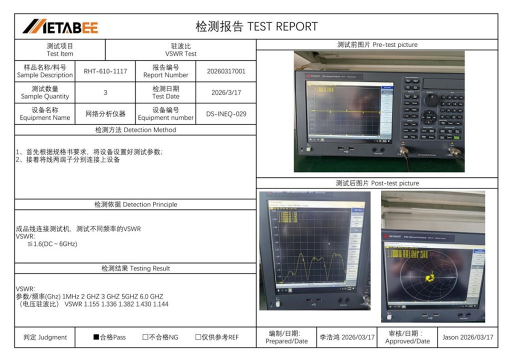
Acceptance Criteria: For a premium BNC connector, such as those engineered by Metabee, the factory standard is strict. The VSWR must remain ≤ 1.6 across the entire DC to 6GHz frequency band. Quality control flags the batch as non-compliant (NG) if the line spikes above 1.6. This failure indicates internal geometry flaws or a severe impedance mismatch.
Test 2: Contact Resistance Testing Process
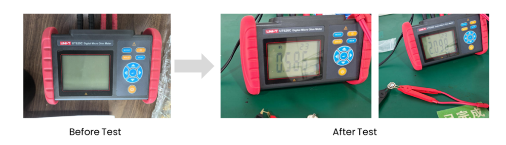
Equipment Required: Digital Micro-ohmmeter equipped with precision Kelvin probes.
The Process:
- Environmental Control: Facilities conduct testing under standard room temperature conditions. Extreme temperatures can artificially affect resistance readings.
- Center Conductor Test: Testers apply the test probes to the connector’s center pin and the mating contact. They pass a precise, low-level current through the connection. Finally, they measure the voltage drop to calculate resistance.
- Outer Conductor Test: Technicians repeat the process for the outer shield. They place the probes directly on the outer metallic body.
Acceptance Criteria: Manufacturers enforce strict micro-ohm limits to ensure optimal signal flow.
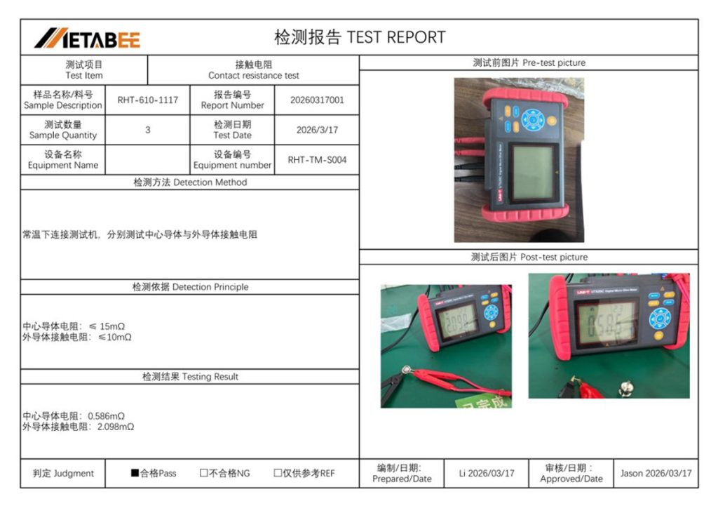
- Center Conductor Resistance: Must be ≤ 15 mΩ. (Top-tier manufacturing often yields exceptional results, such as 0.986 mΩ).
- Outer Conductor Resistance: Must be ≤ 10 mΩ. (Actual test results often yield around 2.098 mΩ).
Connectors failing these metrics often suffer from poor plating, oxidation, or insufficient mechanical tension.
Test 3: Hipot (Insulation) Testing Process
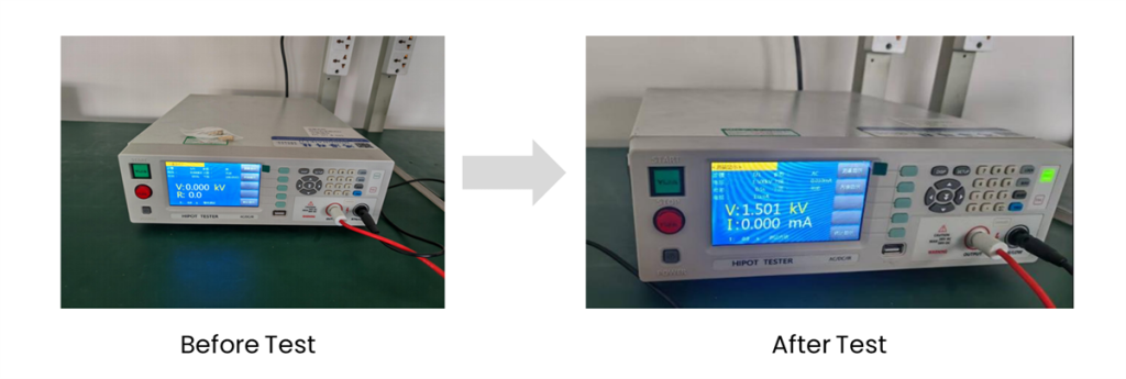
Equipment Required: Dielectric Withstand Voltage Tester (Hipot Tester).
The Process:
- Setup: Operators connect the BNC connector to the testing rig. They attach the high-voltage lead to the center pin. Then, they connect the ground lead to the outer metallic shell.
- Voltage Application: The Hipot machine applies a massive alternating current (AC) voltage across the dielectric. This is typically 1500V AC held for a sustained period of 60 seconds.
- Monitoring: The machine continuously monitors the leakage current escaping through the PTFE insulator during this minute-long stress test.
Acceptance Criteria: The connector must meet two conditions to pass the Hipot test:
- No Breakdown: The insulator must not fail. There must be absolutely no arcing, sparking, or dielectric breakdown.
- Low Leakage Current: The leakage current between the center pin and the outer shell must remain below 0.5 mA.
Passing this test guarantees the BNC connector can safely operate in demanding environments without short-circuiting.
Metabee Test Report Sample
To see what a passing grade looks like in a real-world scenario, examine the sample test report below. This document demonstrates the rigorous data collection process for VSWR, Contact Resistance, and Insulation testing.
Conclusion
Buyers should never procure BNC connectors based on aesthetics or price alone. A connector might look perfect to the naked eye. However, it can easily hide internal flaws, poor plating, or substandard dielectrics that destroy signal integrity.
True reliability is only proven through rigorous, factory-level electrical testing. B2B buyers should demand comprehensive test reports covering VSWR, Micro-ohm Contact Resistance, and Hipot testing. This documentation helps eliminate supply chain risks and ensures systems perform flawlessly.
Ready to upgrade your supply chain with components you can trust? At Metabee, we specialize in providing high-performance electronic connectors and custom wire harnesses. We back every product with stringent, documented quality control. Every batch of our BNC connectors undergoes the exact rigorous testing outlined in this guide.
Don’t compromise your system’s integrity. Contact the Metabee engineering team today. You can request comprehensive factory test reports, discuss your custom applications, or order high-quality BNC connector samples for your own evaluation.
Related Products:
Frequently Asked Questions (FAQs)
Q: Can I use a standard digital multimeter to fully test a BNC connector?
A: No. While a basic multimeter can verify simple continuity or detect direct short circuits, it cannot measure high-frequency performance. You need advanced equipment like a Vector Network Analyzer (VNA) to measure critical parameters like VSWR and signal reflection accurately.
Q: What happens if a BNC connector fails the VSWR test?
A: If a connector fails the VSWR test (typically exceeding a ratio of 1.6), it indicates a severe impedance mismatch. In a real-world application, this causes significant signal reflection. The result is poor power transfer, signal distortion, and potential data packet loss in high-speed digital networks.
Q: Why is contact resistance measured in milliohms (mΩ)?
A: Contact resistance must be exceptionally low to ensure unhindered signal flow. Resistance measured in whole Ohms would signify a severely degraded connection. High resistance (above 15 mΩ for the center pin) causes signal attenuation and can generate dangerous heat during power transmission.
Q: How do I request a factory test report for BNC connectors?
A: When sourcing components, you should always ask your manufacturer or supplier directly for their Quality Assurance documentation. Reputable manufacturers like Metabee can easily provide detailed test reports covering VSWR, contact resistance, and Hipot testing for their product batches.
