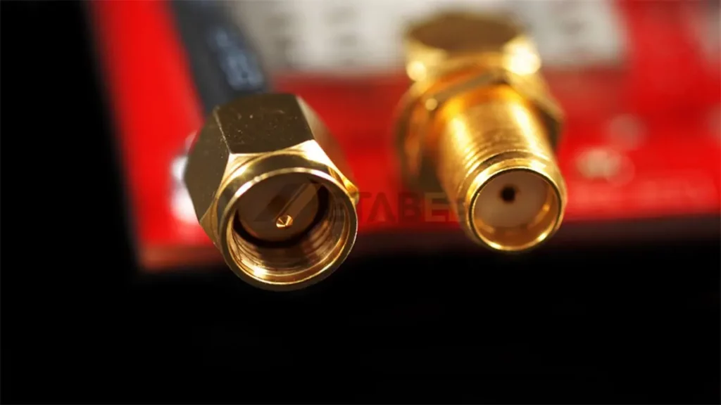
RF and microwave systems rely heavily on robust and reliable connections to transmit signals efficiently. Among the various types of RF connectors available, the SMA connector stands out as a widely used and versatile choice. This guide will delve into the different types of SMA connectors, exploring their key features, applications, and how they compare to other RF connection solutions. Understanding these distinctions is crucial for engineers and technicians to select the most appropriate connector for their specific needs.
Introduction to SMA Connectors
The SMA connector is one of the most important connectors in RF systems. In this section, we will delve deeper into the specifics of this widely used component, providing a solid foundation for understanding its various types and applications
SMA Connector Meaning
The acronym “SMA” stands for SubMiniature version A. Developed in the 1960s, the SMA connector was designed to provide a reliable and durable connection for RF signals in a compact form factor. Its initial purpose was to meet the growing need for smaller, yet high-performing, connectors in the burgeoning field of microwave technology. Over the decades, the SMA connector has become a de facto standard in many industries, due to its reliable performance and efficient design.
Key Features and Characteristics
The success and widespread adoption of SMA connectors can be attributed to several key features and characteristics that make them ideal for RF applications:
- Threaded Coupling Mechanism
- 50 Ohm Impedance
- Compact Size and Weight
- Up to 18 GHz Frequency Range
- Durability and Reliability
- Ease of Use
Common Applications in RF and Microwave Systems
Due to their versatility and reliability, SMA connectors are used in a vast array of applications, including:
- Wireless communication systems (e.g., Wi-Fi, Bluetooth)
- Satellite communication equipment
- Test and measurement instruments
- Antennas and antenna systems
- RF amplifiers and filters
- Microwave components
- Military and aerospace applications
Related Post: What is an SMA Connector? Everything You Need to Know
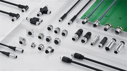
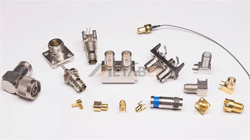
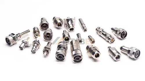
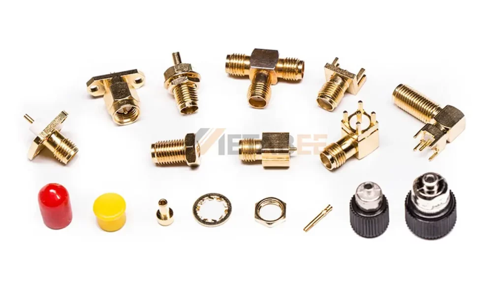
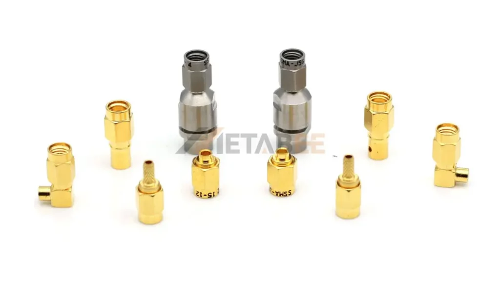
16 Popular Types of SMA Connectors
SMA connectors come in various configurations to suit different application requirements. Here are 16 popular types categorized based on key characteristics:
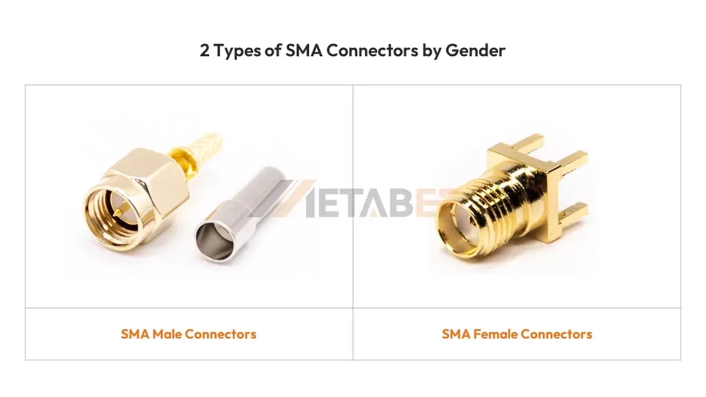
Based on Gender
The gender of an SMA connector refers to the type of center contact.
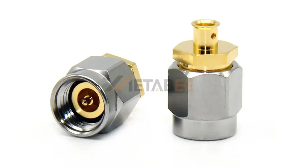
SMA Male Connectors
An SMA male connector has a center pin that protrudes from the connector body. This pin fit into the center receptacle of a female SMA connector. The external body of the SMA male connector typically has internal threads for mating with the external threads of an SMA female connector.
Key Features: Center pin, internal threads on the body.
SMA Female Connectors
A female SMA connector has a center receptacle that accepts the center pin of a male connector. The external body of the female connector typically has external threads for mating with the internal threads of a male connector.
Key Features: Center receptacle, external threads on the body.
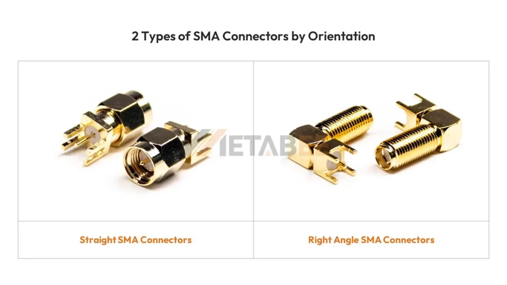
Based on Orientation
The orientation of an SMA connector describes the direction in which the cable or the connector body extends.
Straight SMA Connectors
Straight SMA connectors have the cable or the mounting interface extending directly in a linear fashion from the connector body. The signal path is essentially a straight line through the connector.
Key Features: Linear extension of the cable or mounting interface.
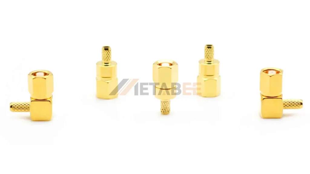
Right-Angle SMA Connectors
Right-angle SMA connectors have the cable or mounting interface extending at a 90-degree angle from the connector body. They are useful in space-constrained applications.
Key Features: 90-degree angle from the connector body.
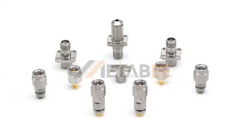
Based on Mounting Style
The mounting style describes how the SMA connector is physically attached to a panel, printed circuit board (PCB), or a coaxial cable. The choice of mounting style depends on the specific design and integration requirements of the RF system.
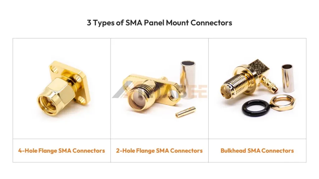
Panel Mount SMA Connectors
Panel mount SMA connectors are designed to be mounted through a panel or chassis.
4-Hole Flange SMA Connectors
These panel mount SMA connectors feature a flange with four mounting holes, typically located around the circumference of the connector body. This provides a secure and stable mounting to the panel.
Key Features: Four mounting holes on a flange.
2-Hole Flange SMA Connectors
Similar to 4-hole flange SMA connectors, but with only two mounting holes on the flange. This can be a more space-efficient option or used when fewer mounting points are sufficient.
Key Features: Two mounting holes on a flange.
Bulkhead SMA Connectors
Bulkhead SMA connectors are designed to pass through a panel. They provide a connection point on the equipment enclosure’s inside and outside. They often have a sealing mechanism to maintain the integrity of the enclosure.
Key Features: Passes through a panel, provides connections on both sides, often with sealing.
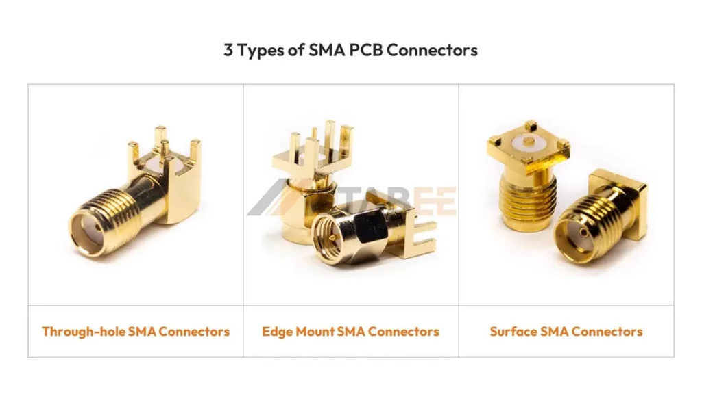
SMA PCB Connectors
PCB mount SMA connectors are designed to be soldered directly onto a printed circuit board.
Through-Hole SMA Connectors
SMA through-hole connectors have pins that extend through holes drilled in the PCB and are soldered on the opposite side of the board. This provides a strong mechanical connection to the PCB.
Key Features: Pins that pass through the PCB.
Edge Mount SMA Connectors
Edge mount SMA connectors are soldered to the edge of the PCB. They provide a connection that is parallel to the board surface. This can be useful in designs where a low profile or specific board layout is required.
Key Features: Mounted on the edge of the PCB, parallel to the board surface.
Surface Mount SMA Connectors
Surface mount SMA connectors have solder pads on the bottom that are soldered directly to the surface of the PCB.
Key Features: Solder pads on the bottom for surface mounting.
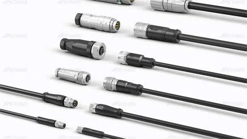
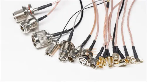
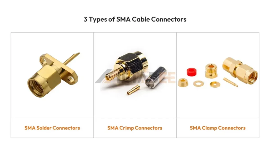
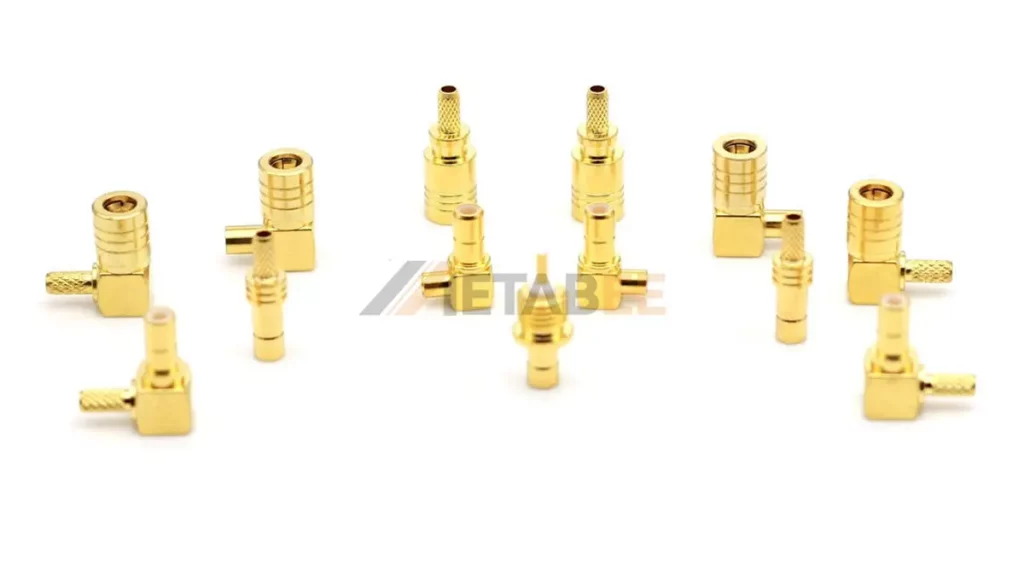
Cable Mount SMA Connectors
Cable mount SMA connectors are designed to be attached to the end of a coaxial cable.
SMA Solder Connectors
SMA solder connectors use solder to attach the center conductor and outer shield of the cable.
Key Features: Uses solder for cable attachment.
SMA Crimp Connectors
SMA crimp connectors utilize a specialized crimping tool to compress the connector onto the cable, creating a secure mechanical and electrical connection. This method is often faster and more efficient for mass production or field installations.
Key Features: A crimping tool is used for cable attachment.
SMA Clamp Connectors
SMA clamp connectors use a clamping mechanism to mechanically secure the cable to the connector. This method often does not require soldering and can be convenient for field installations or when soldering is not preferred.
Key Features: Uses a clamping mechanism for cable attachment.
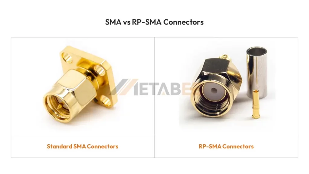
Based on Polarity
The polarity of an SMA connector refers to the configuration of the center contact.
Standard SMA Connectors
Standard SMA connectors follow the conventional gender assignment: male has a center pin, and female has a center receptacle. This is the most common type of SMA connector.
Key Features: Standard center pin and receptacle configuration.
Reverse Polarity SMA (RP-SMA) Connectors
RP-SMA connectors have the gender of the center contact reversed compared to standard SMA connectors. A male RP-SMA connector has a center receptacle, and a female RP-SMA connector has a center pin. This is often used to prevent accidental mating with standard SMA connectors. RP-SMA Connectors are common in Wi-Fi and other wireless devices.
SMA vs RP-SMA
The primary difference lies in the gender of the center contact. Standard SMA connectors follow the typical male/female convention, while RP-SMA connectors invert this.
Hermetic SMA Connectors
Hermetic SMA connectors have a sealed interface to prevent the ingress of moisture, gases, or other contaminants. They are suitable for applications where environmental sealing is critical, such as in aerospace or harsh industrial environments.
By understanding these various types of SMA connectors and their specific characteristics, engineers and technicians can make informed decisions when designing and implementing RF systems, ensuring optimal performance and reliability for their applications.
High-Frequency RF Connectors Related to SMA
While SMA connectors offer a frequency range up to DC-18 GHz, they fall short of meeting the demands for higher frequencies. Consequently, the development of connectors capable of supporting higher frequencies became necessary. Examples of these include 3.5mm, 2.92mm, 2.4mm, 1.85mm, and 1.0mm connectors. Understanding these related high-frequency connectors is crucial for engineers working on advanced RF and microwave systems.
3.5mm Connectors
3.5mm connectors (also known as SMA 3.5mm connectors) are a precision RF connector designed for use up to 26.5 GHz. They are mechanically compatible with SMA connectors. But they offer improved performance at higher frequencies due to their more precise construction and tighter tolerances.
Key Features:
- Higher Frequency Range: up to 26.5 GHz, significantly higher frequencies than standard SMA.
- Precision Construction: Built with tighter tolerances and more precise manufacturing to minimize signal reflections and losses at higher frequencies.
- Mechanical Compatibility with SMA: SMA 3.5mm connectors are mechanically compatible with SMA connectors. However, it’s important to note that mating a 3.5mm male with an SMA female will result in the performance being limited to the lower frequency capabilities. For optimal performance at higher frequencies, mating 3.5mm with 3.5mm is recommended.
- Air Dielectric: Often utilizes an air dielectric or a low-loss dielectric material.
2.92mm (K-connectors, or SMK Connectors) Connectors
2.92mm (also known as K-connectors or SMK connectors) connectors are suitable for even higher frequencies, operating up to 46 GHz. They offer excellent performance and are often used in test and measurement equipment. They are also mechanically compatible with SMA and 3.5mm connectors.
Key Features:
- Very High Frequency Operation: Capable of handling frequencies up to 46 GHz, making it suitable for a wide range of microwave applications.
- Excellent Return Loss: Designed to provide excellent return loss (low signal reflection) at these higher frequencies.
- Mechanical Compatibility with SMA and 3.5mm: Similar to 3.5mm connectors, 2.92mm connectors are mechanically compatible with SMA and 3.5mm connectors. However, as with the 3.5mm, mating with SMA will limit the performance to the lower frequency range.
- Air Dielectric: Typically employs an air dielectric for low loss.
2.4mm Connectors
2.4mm connectors provide high-performance operation up to 50 GHz. They offer excellent return loss and are suitable for demanding high-frequency applications.
Key Features:
- Ultra-High Frequency Operation: Capable of operating at frequencies up to 50 GHz, catering to the needs of the most demanding high-frequency systems.
- Superior Performance: Offers excellent return loss and insertion loss characteristics at these ultra-high frequencies.
- Precision Construction: Manufactured with very tight tolerances to maintain signal integrity at these high frequencies.
- Non-Compatible with SMA/3.5mm/2.92mm: Unlike the 3.5mm and 2.92mm, 2.4mm connectors are not mechanically compatible with SMA, 3.5mm, or 2.92mm connectors. They have their own unique mating interface designed for optimal performance at their specified frequency range.
1.85mm Connectors
1.85mm (also known as V-type) connectors are designed for high frequencies, up to 67 GHz. They are used in advanced research and development and high-end test equipment.
Key Features:
- Extremely High Frequency Operation: Designed for the millimeter-wave frequency range.
- Exceptional Performance: Engineered for minimal signal loss and reflection at these extreme frequencies.
- Highly Precision Construction: Requires extremely tight tolerances in manufacturing.
- Non-Compatible with SMA/3.5mm/2.92mm/2.4mm: Similar to the 2.4mm connector, the 1.85mm connector has a unique mating interface. It is incompatible with lower-frequency connectors like SMA.
1.0mm Connectors
1.0mm (also known as W type) connectors are the highest frequency coaxial connectors commonly available, operating up to 110 GHz. They are used in the most advanced millimeter-wave applications.
Key Features:
- Ultra-High Frequency Operation: Operates in the extremely high millimeter-wave band.
- State-of-the-Art Performance: Engineered for minimal signal degradation at these extremely high frequencies.
- Highly Specialized Construction: Requires extremely precise manufacturing and materials.
- Non-Compatible with SMA/3.5mm/2.92mm/2.4mm/1.85mm Connectors: Has its unique mating interface.
Comparison with SMA
SMA connectors are robust and versatile. But their performance characteristics, particularly in terms of insertion loss and return loss, degrade at higher frequencies. The related high-frequency connectors discussed above are specifically designed to overcome these limitations. They provide superior performance in the microwave and millimeter-wave frequency ranges.
In the following table, I have compared SMA/3.5mm/2.92mm/2.4mm/1.85mm/1.0mm connectors:
| Feature | SMA Connector | 3.5mm Connector | 2.92mm (K-connector) Connector | 2.4mm Connector | 1.85mm Connector | 1.0mm Connector |
|---|---|---|---|---|---|---|
| Frequency Range | Up to 18 GHz | Up to 26.5 GHz | Up to 46 GHz | Up to 50 GHz | Up to 67 GHz | Up to 110 GHz |
| Impedance | 50 Ohm | 50 Ohm | 50 Ohm | 50 Ohm | 50 Ohm | 50 Ohm |
| Mechanical Coupling | Threaded | Threaded | Threaded | Threaded | Threaded | Threaded |
| Mating Compatibility | Mates with 3.5mm, 2.92mm | Mates with SMA, 2.92mm | Mates with SMA, 3.5mm | Not compatible with others | Not compatible with others | Not compatible with others |
| Precision | Standard | Higher Precision | Higher Precision | Very High Precision | Extremely High Precision | Extremely High Precision |
| Typical Applications | General RF and Microwave applications | Test & Measurement, Microwave links | Test & Measurement, Microwave links, R&D | Advanced Test & Measurement, Millimeter-wave | Millimeter-wave R&D, Instrumentation | Advanced Millimeter-wave R&D, Instrumentation |
| Primary Advantage | Versatile, Cost-effective | Higher Frequency Performance | Higher Frequency Performance | Ultra-High Frequency Performance | Extremely High Frequency Performance | Highest Frequency Performance |
| Primary Limitation | Performance degrades at higher frequencies | Less performance at very high frequencies than others | Less performance at very high frequencies than others | Not compatible with lower frequency connectors | Not compatible with lower frequency connectors | Not compatible with lower frequency connectors |
Related RF Connector Types
Beyond the high-frequency alternatives, other RF connector families share some similarities with SMA connectors. They are designed for different application requirements or offer distinct features. Understanding these related connector types can broaden your understanding of the RF connection landscape. It also helps you choose the most suitable connector for your specific needs.
SSMA Connectors
The SSMA (SubSubMiniature version A) connector is, as the name suggests, a smaller version of the SMA connector. It provides better performance characteristics than SMA but in a more compact form factor.
Key Features:
- Better Performance: SSMA connectors offer better electrical performance than SMA connectors. Their frequency range is typically up to 35 GHz.
- Threaded Coupling: Like SMA, SSMA connectors utilize a 10-36 threaded coupling mechanism for a secure and reliable connection.
- 50 Ohm Impedance: Generally designed with a 50-ohm impedance.
SMB Connectors
SMB (SubMiniature B) connectors are another subminiature RF connector family, but they utilize a snap-on coupling mechanism instead of a threaded one. This allows for quicker and easier mating.
Key Features:
- Snap-on Coupling: Provides a quick and convenient connection and disconnection.
- Compact Size: Similar in size to SMA connectors.
- Lower Frequency Range: Generally designed for applications up to 4 GHz.
- 50 Ohm and 75 Ohm Impedances: Available in both 50-ohm and 75-ohm impedance versions to suit different system requirements.
SMC Connectors
SMC (SubMiniature C) connectors feature a #10-32 UNF threaded coupling mechanism similar to SMA, providing a secure connection. They are often used in similar applications to SMA but may have slightly different performance characteristics.
Key Features:
- Threaded Coupling: Provides a secure and reliable connection, similar to SMA.
- Compact Size: Similar in size to SMA and SMB connectors.
- Lower Frequency Range: While offering a typical DC-4GHz frequency range, it is generally lower than the typical SMA range.
- 50 Ohm and 75 Ohm Impedances: Like SMB connectors, SMC connectors are available in both 50-ohm and 75-ohm impedance versions.
SMA vs SSMA vs SMB vs SMC
Comparison Summary:
| Feature | SMA | SSMA | SMB | SMC |
|---|---|---|---|---|
| Coupling | Threaded | Threaded | Snap-on | Threaded |
| Size | – | Smaller than SMA | Smaller than SMA | Smaller than SMA |
| Frequency | Up to ~18 GHz | Up to ~35 GHz | Up to ~4 GHz | Up to ~4 GHz |
| Impedance | 50 Ohm | 50 Ohm | 50 Ohm and 75 Ohm | 50 Ohm and 75 Ohm |
| Security | Very Secure, Vibration Resistant | Secure, Vibration Resistant | Quick Connect, Less Vibration Resistant | Secure, Vibration Resistant |
| Ease of Use | Requires wrench for tightening | Requires wrench for tightening | Quick connect/disconnect | Requires wrench for tightening |
| Typical Use | General RF applications, higher freq. | Space-constrained, higher performance | Quick connections, lower frequency | Secure connections, lower frequency |
Related Products
- SMA Connectors
- SMA Adapters
- SMA cable assemblies
- 2.92mm (K-connectors, or SMK Connectors) Connectors
- SSMA Connectors
- SMB Connectors

Conclusion
SMA connectors are a cornerstone of RF and microwave connectivity. They offer a reliable and versatile solution for a wide range of applications. Understanding the different types of SMA connectors is essential for selecting the right connector for your specific needs. Furthermore, being aware of related high-frequency and alternative connector types allows engineers and technicians to make informed decisions for optimal system performance. By considering these factors, you can ensure robust and efficient signal transmission in your RF designs.
Pingback: The Ultimate Guide to 2.92mm Connectors - MetabeeAI
Pingback: What is an N-type connector? A Deep Dive - MetabeeAI