SMA connectors are a type of coaxial RF connector widely used in various electronic applications, particularly in the radio frequency (RF) and microwave industries. They are known for their reliable performance, durability, and versatility. This article will delve into the details of SMA connectors, covering their definition, specifications, types, applications, and more.
- SMA Connector Meaning
- Main Specifications of SMA Connectors
- SMA Connector Interface Dimensions
- SMA Connector Types
- RP-SMA VS SMA Connectors
- SMA VS SMB VS SMC Connectors
- 5 Common Variations of SMA Connectors
- SMA Connector Manufacturers
- Applications
- How to Choose the Right SMA Connectors?
- Conclusion
- Related Products
SMA Connector Meaning
Definition
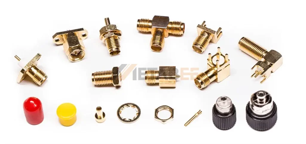
An SMA connector is a type of coaxial RF connector developed in the 1960s. It employs a threaded coupling mechanism to establish a secure and reliable connection.
The acronym “SMA” stands for “Sub-Miniature version A” indicating its compact size. So, the full form name of SMA Connectors is Sub-Miniature version A connectors.
According to the MIL-STD-348 standard, the SMA connector’s interface features a 1/4-36 thread specification. This means it utilizes a threaded barrel with a 1/4-inch diameter and 36 threads per inch for secure and precise connections. This threaded interface ensures a robust mechanical bond, minimizing the risk of accidental disconnections.
Standard
SMA connectors are standardized according to specifications like MIL-PRF-39012 and CECC 22110/111. However, the industry has evolved to meet diverse needs, resulting in a wide range of variants, including field-replaceable versions and commercial-grade connectors. Despite these variations, the fundamental interface dimensions remain standardized as outlined in MIL-STD-348. This standard ensures compatibility and interchangeability between different manufacturers’ SMA connectors.
Main Features
- Compact Size: SMA connectors are characterized by their small form factor, making them suitable for space-constrained applications.
- Robust Construction: The threaded coupling mechanism provides a secure and durable connection, capable of withstanding harsh environmental conditions.
- Excellent RF Performance: SMA connectors exhibit low insertion loss, high impedance matching, and minimal signal reflections, ensuring optimal signal integrity.
- Wide Frequency Range: These connectors can accommodate a broad spectrum of frequencies, typically ranging from DC to 18 GHz.
- Versatility: SMA connectors are available in various configurations, including cable-mount, panel-mount, and PCB-mount styles, catering to diverse installation requirements.
Main Specifications of SMA Connectors
To ensure optimal performance in various applications, SMA connectors adhere to specific electrical and mechanical specifications.
Frequency Range
The SMA connector was originally designed for use from DC (0 Hz) to 12 GHz, but its frequency range has been extended over time. Nowadays, the SMA connector is typically rated for mode-free operation from DC to 18 GHz, though some proprietary versions are rated to 26.5 GHz.
While standard SMA connectors are typically rated for frequencies up to 18 or 26.5 GHz, some variants, such as 2.92mm connectors, can handle even higher frequencies, reaching up to 46 GHz.
Need a higher-frequency SMA connector? Metabee can help. We offer a wide range of standard SMA connectors and can also design and manufacture custom solutions to meet your exact requirements. Contact us now!
Impedance
The standard impedance for SMA connectors is 50 ohms, which is a common impedance for RF systems. This impedance matching minimizes signal reflections and ensures efficient power transfer.
VSWR
VSWR stands for Voltage Standing Wave Ratio, which is a measure of the impedance match between a transmission line and a load.
A lower VSWR indicates better impedance matching and reduced signal reflections. Ideal VSWR values for SMA connectors are close to 1. A high VSWR can lead to signal distortion, power loss, and potential damage to connected components.
Straight SMA connectors typically have a VSWR of 1.3 or less, while right angle SMA connectors generally have a VSWR of 1.5 or less.
Voltage Rating
There are two key parameters: dielectric withstanding voltage and operating voltage.
Dielectric Withstanding Voltage
The dielectric withstanding voltage of SMA connectors typically ranges from 500V to 1000V. The specific value depends on the matching cable type. A typical range is shown in the table below:
| Matching Cables | Dielectric Withstanding Voltage |
|---|---|
| RG142, RG405 | 1000V rms min. |
| RG316, RG402 | 750V rms min. |
| RG178 | 500 V rms min. |
Operating Voltage
The operating voltage of SMA connectors ranges from 170V to 500V. This value also depends on the matching cable type. Typical working voltage values are shown in the table below.
| Matching Cables | Operating Voltage |
|---|---|
| RG142, RG405 | 500V rms min. |
| RG316, RG402 | 375V rms min. |
| RG178 | 170V rms min. |
Insertion Loss
Insertion loss of SMA connectors refers to the reduction in signal power when an SMA connector is inserted into a transmission line. In simpler terms, it’s the amount of signal strength lost as the signal passes through the connector. The insertion loss is expressed in decibels (dB).
SMA connectors are known for their low insertion loss. Typical values range from 0.1 dB to 0.5 dB.
The insertion loss calculator of SMA connectors is as follows:

The insertion loss requirement for SMA connectors, when tested at 6 GHz, is defined as 0.06 multiplied by the square root of the frequency in GHz. This means that at a frequency of 4 GHz, the maximum allowable insertion loss is 0.06 * √4 = 0.12 dB.
Power Handling Capability
SMA Connector Power Handling Capability is the ability of a SMA connector to pass high currents and keep heat rising at a moderate temperature. SMA connectors can handle a wide range of power levels, from low-power applications to high-power systems. The specific power handling capability depends on factors such as connector design, materials, and cooling techniques. Exceeding the power rating can lead to overheating, connector damage, and potential system failure.
The power handling capability of SMA connectors is presented in the table below.
| Contact Gauge | Series | Contact Diameter Inch | Current (Amps) 10 deg C temp rise | Current (Amps) 35 deg C temp rise | Current (Amps) 140 deg C temp rise |
|---|---|---|---|---|---|
| 19 | SMA | 0.036 | 4.8 | 85 | 16 |
Materials
An SMA connector consists of three main components: the outer shell, the center contact, and the insulator. The choice of materials for each component varies, contributing to the connector’s overall performance and application.
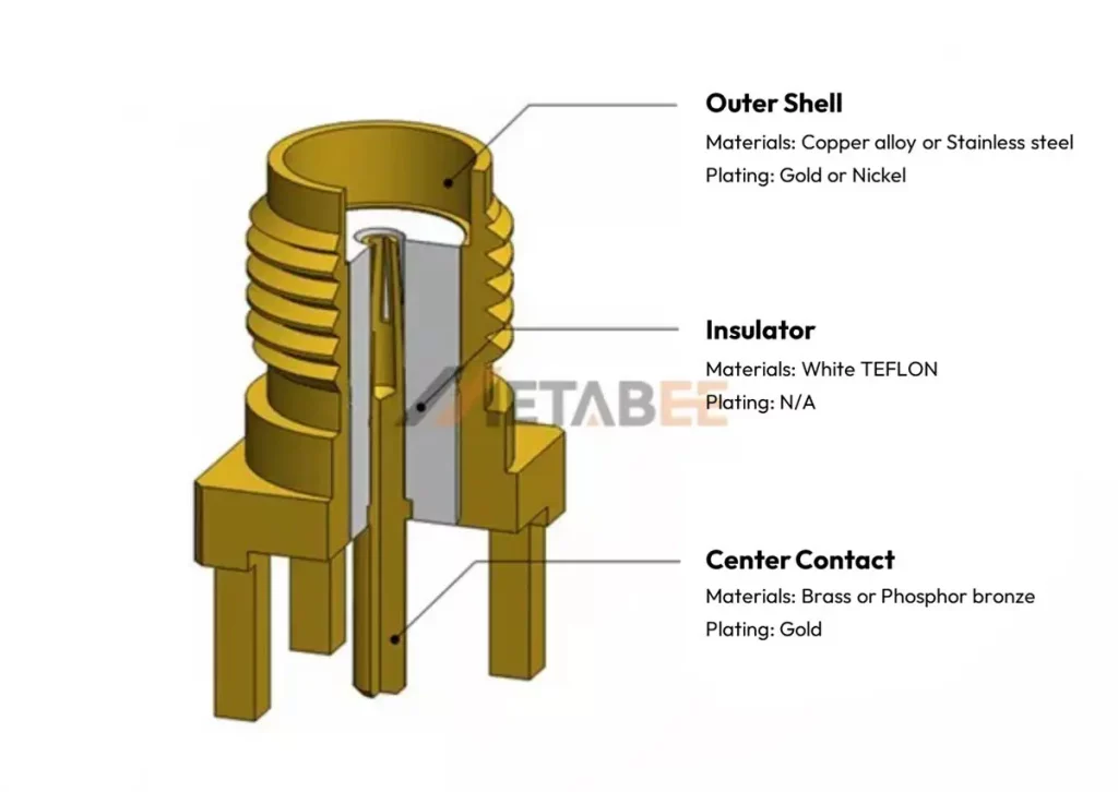
- Outer Shell: The materials of the outer shell is commonly copper alloy or stainless steel. These materials provide mechanical strength. The surface is often plated with gold or nickel to improve corrosion resistance.
- Center Contact: The material of the center contact, or pin, is usually brass or phosphor bronze. These materials offer good electrical conductivity and mechanical properties. A gold plating is commonly applied to enhance conductivity and prevent oxidation.
- Insulator: The insulating material used in SMA connectors is typically white Teflon. Teflon offers excellent dielectric properties, chemical resistance, and a wide operating temperature range.
Main Materials of SMA Connectors:
| Component | Material | Plating | Purpose |
|---|---|---|---|
| Outer Shell | Copper alloy or Stainless steel | Gold or Nickel | Mechanical strength, corrosion resistance |
| Center Contact | Brass or Phosphor bronze | Gold | Electrical conductivity, wear resistance |
| Insulator | Teflon | N/A | Electrical insulation, chemical resistance, temperature stability |
At Metabee, we are committed to using only the highest quality materials in our SMA connectors. By carefully selecting materials with superior electrical and mechanical properties, we are able to produce connectors that meet the most demanding applications.
Mating Cycles
The mating cycle of an SMA connector refers to the number of times it can be connected and disconnected without compromising performance. A typical SMA connector can withstand over 500 mating cycles. Factors like design, material quality, and manufacturing precision influence this durability.
Torque
Proper torque is crucial for ensuring a secure and reliable connection. Exceeding the recommended torque can damage the connector threads, while insufficient torque can lead to poor electrical contact and increased insertion loss. Torque wrenches are often used to apply the correct amount of torque during assembly.
To ensure optimal performance and a secure connection, Metabee SMA connectors require a minimum coupling torque of 30 in-lbs.
By understanding these key specifications, you can select the appropriate SMA connectors for their specific application needs and ensure optimal system performance.
SMA Connector Interface Dimensions
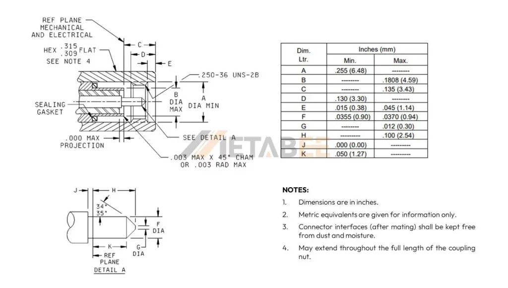
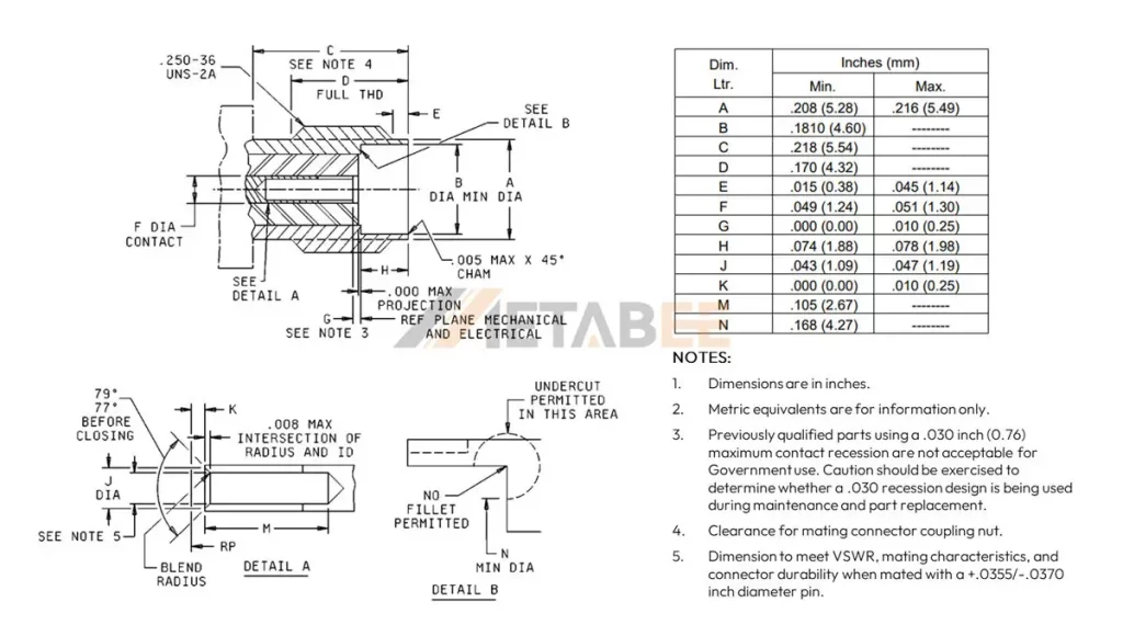
The Interface dimensions of SMA connectors are standardized to ensure compatibility. The specific dimensions for male and female connectors can be found in the MIL-STD-348 standard.
SMA Male / Plug Connector Interface Dimensions
SMA Female / Jack Connector Interface Dimensions
SMA Connector Types
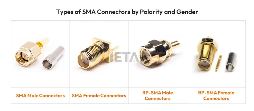
SMA connectors are available in various configurations to meet diverse application requirements. Here are the 7 primary types of SMA connectors:
By Polarity and Gender
Standard-Polarity SMA Connectors:
In standard-polarity SMA connectors, the center conductor of a male connector is a pin, while the center conductor of a female connector is a socket. This is the most common type of SMA connector and is widely used in various RF applications.
- SMA Male Connectors: These connectors have a center pin contact that inserts into the mating female connector.
- SMA Female Connectors: These connectors have a center socket contact that receives the male pin.
Reverse-Polarity RP-SMA Connector:
In reverse-polarity RP-SMA connectors, the polarity of the center conductor is reversed compared to standard SMA connectors. So, a male RP-SMA connector has a socket as the center conductor, while a female RP-SMA connector has a pin.
- RP-SMA Male Connectors: These connectors have a center socket contact, which is inverted compared to standard SMA connectors.
- RP-SMA Female Connectors: These connectors have a center pin contact, mating to RP-SMA male connectors.
By Mounting Method
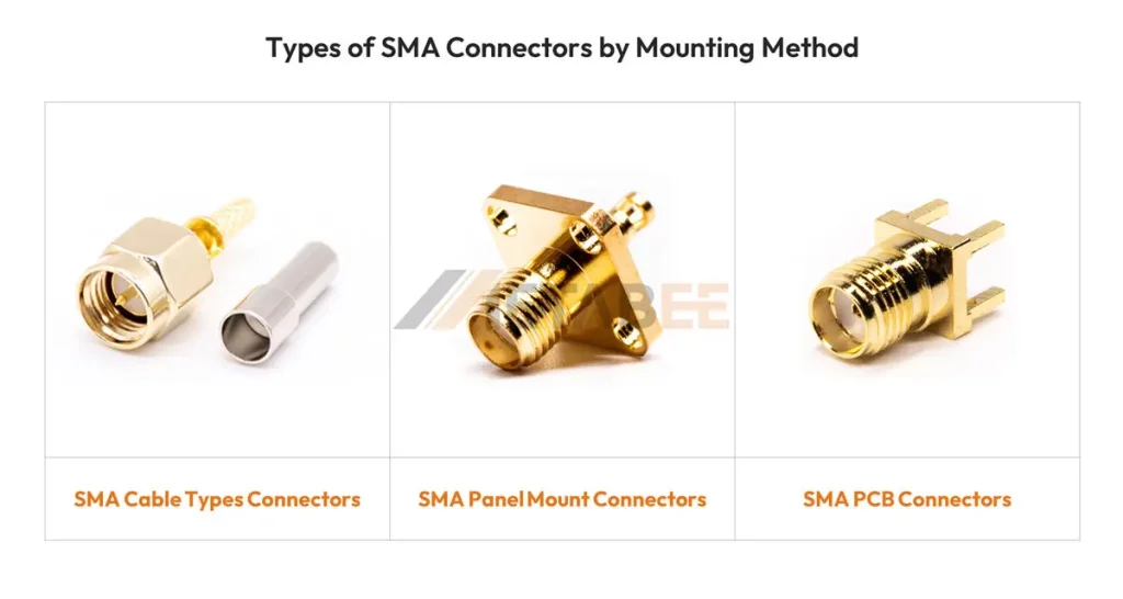
- SMA Cable Type Connectors: These connectors are designed to be directly soldered or crimped onto a coaxial cable, providing a flexible and customizable solution. Depending on the termination method, these connectors can be categorized into SMA solder connectors, SMA crimp connectors, SMA clamp connectors, and so on.
- SMA Panel Mount Connectors: These connectors are designed to be mounted on a panel or chassis, offering a secure and rigid connection. Based on their mounting features, these connectors can be further categorized into SMA bulkhead connectors and SMA flange connectors.
- SMA PCB Connectors: These connectors are designed for surface mount or through-hole mounting on a printed circuit board, enabling integration into compact electronic devices. We can further categorize these connectors into through-hole SMA PCB connectors, surface-mount SMA PCB connectors, and edge-mount SMA PCB connectors.
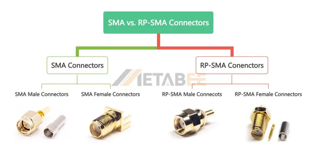
To quickly identify different types of SMA connectors, I’ve created a mind map categorizing the 7 most common types.

RP-SMA VS SMA Connectors
RP-SMA connectors are reverse-polarity versions of SMA connectors. This means the center pin and contact are reversed, preventing accidental mating with standard SMA connectors.
- Standard-polarity SMA Connectors: the center conductor of a male connector is a pin, while the center conductor of a female connector is a socket.
- Reverse-polarity RP-SMA Connectors: A male RP-SMA connector has a socket as the center conductor, while a female RP-SMA connector has a pin.
Key Difference of SMA and RP-SMA Connectors:
| Feature | Standard-polarity SMA | Reverse-polarity RP-SMA |
|---|---|---|
| Center conductor of male connector | Pin | Socket |
| Center conductor of female connector | Socket | Pin |
| Compatibility | Compatible with other standard-polarity SMA connectors | Not compatible with standard-polarity SMA connectors |
| Applications | Wide range of RF applications, including telecommunications, test equipment, and industrial electronics. | Often used in wireless communication devices, such as antennas for mobile phones and Wi-Fi routers. |
Metabee provides a comprehensive selection of standard SMA and RP-SMA connectors to meet various application requirements.
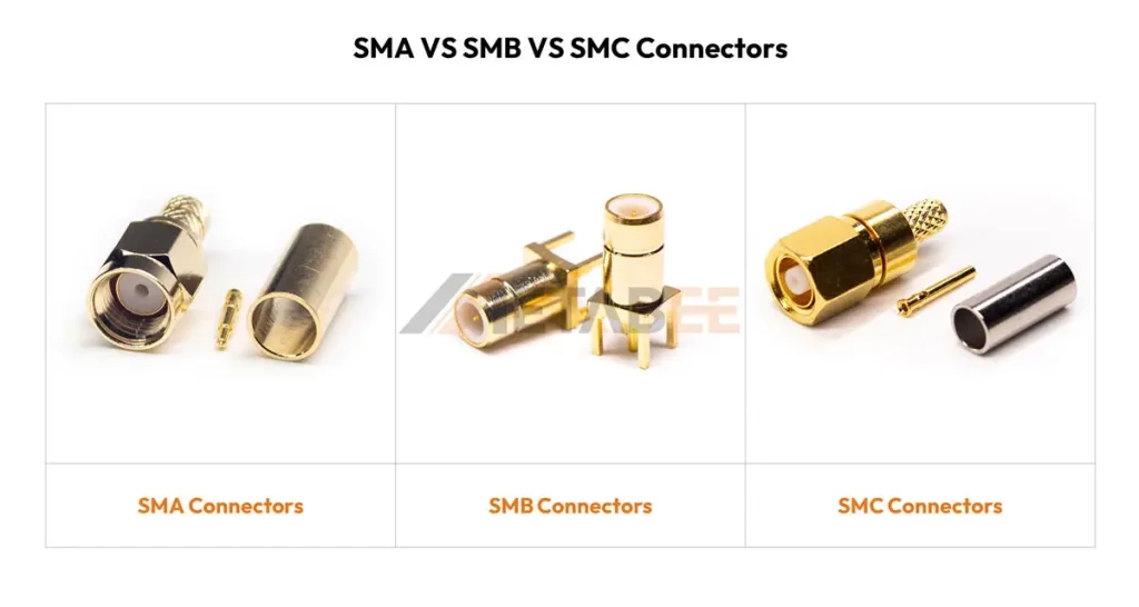
SMA VS SMB VS SMC Connectors
SMA, SMB, and SMC connectors are all coaxial RF connectors that differ in their coupling mechanism, impedance, and operating frequency.
SMB Connectors
SMB connectors offer a balance of performance and cost-effectiveness. They feature a push-on (snap-on) mating mechanism, making them quicker and easier to connect and disconnect than SMA connectors. While they are suitable for a wide range of RF applications, including computer peripherals and consumer electronics, they may not be as durable as SMA connectors, especially in harsh environments. Besides, the popular automobile connector – FAKRA used SMB connector as a core with plastic housing.

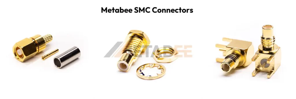
SMC Connectors
Introduced in the 1980s, SMC connectors provide a higher performance alternative to SMA connectors. With a threaded coupling interface, SMC connectors offer excellent broadband performance up to 26 GHz. So, they are often used in high-frequency applications where size and weight are critical factors.
Key Differences of SMA, SMB, and SMC Connectors
| Feature | SMA | SMB | SMC |
|---|---|---|---|
| Mating Mechanism | Screw-on | Snap-on | Screw-on |
| Frequency Range | Up to 18 GHz | Up to 4 GHz | Up to 26 GHz |
| Durability | High | Medium | High |
| Cost | Higher | Lower | Higher |
In summary, while all three types of connectors are widely used in RF applications, the optimal choice depends on specific requirements such as frequency range, durability, and cost. SMA connectors offer superior performance at high frequencies, SMB connectors provide a balance of performance and cost, and SMC connectors offer high performance in a smaller package.
5 Common Variations of SMA Connectors
While standard SMA connectors are widely used, several variations have been developed to meet specific application needs. Here are five common variations of SMA connectors:
3.5 mm Connectors:
These heavy-duty coaxial connectors offer mode-free operation up to 34 GHz. With a 3.5mm outer conductor diameter and an air dielectric interface, they provide a reliable and high-performance connection. Besides, 3.5 mm RF conenctors are compatible with both SMA and 2.92mm connectors.
2.92 mm Connectors (also known as 2.9 mm, K type, or SMK):
These RF/microwave coaxial connectors offer mode-free operation up to 40 GHz and are interoperable with both SMA and 3.5mm connectors.
2.4 mm Connectors:
These 50-ohm, screw-on precision connectors are designed for high-frequency applications up to 50 GHz. Standardized according to IEC 61169-40, they find use in various industries, including satellite communications, test and measurement equipment, and radar systems. While mechanically compatible with 1.85 mm connectors, they are not directly compatible with SMA, 3.5 mm, or 2.92 mm connectors without the use of adapters.
1.85 mm Connectors (also known as V type):
These coaxial connectors offer mode-free operation up to 67 GHz. With an M7 thread, they are mechanically compatible with 2.4mm connectors.
1.0 mm Connectors:
They are 50-ohm precision connectors that operate mode-free up to 110 GHz. They have an outer conductor that measures 1.0 mm and an air dielectric with contact supported by a short dielectric bead.
Key Differences:
| Feature | SMA | 3.5mm | 2.92mm | 2.4mm | 1.85mm | 1.0mm |
|---|---|---|---|---|---|---|
| Size | Small | Small | Small | Very small | Very small | Extremely small |
| Frequency Range | DC to 18 GHz | DC to 34 GHz | DC to 46 GHz | DC to 50 GHz | DC to 65 GHz | DC to 110 GHz |
| Compatibility | Standard | Compatible with SMA and 2.92 mm | Compatible with SMA and 3.5 mm | Compatible with 1.85mm | Compatible with 2.4mm | Specialized |
| Impedance | 50 Ohms | 50 Ohms | 50 Ohms | 50 Ohms | 50 Ohms | 50 Ohms |
SMA Connector Manufacturers
Main Manufacturers
SMA connectors are widely used in radio frequency (RF) applications, and many manufacturers produce them. Here are some of the leading manufacturers in this field, including:

Why choose Metabee?
- High Quality: Metabee is committed to providing high-quality SMA connectors that meet or exceed industry standards.
- Wide Range: We offer a diverse range of SMA connectors to suit various applications and customer requirements.
- Custom Solutions: We can provide custom-designed SMA connectors to meet specific customer needs.
- Competitive Pricing: We offer competitive pricing without compromising on quality.
- Excellent Customer Support: Metabee provides excellent customer support and technical assistance.

Applications
SMA connectors are widely used in various applications, including:
- Wireless communication systems
- Radar systems
- Satellite communication systems
- Test and measurement equipment
- Medical equipment
- Aerospace and defense systems
How to Choose the Right SMA Connectors?
When choosing SMA connectors, consider the following factors:
- Frequency range: Ensure the connector can handle the required frequency.
- Impedance: Select a connector with the appropriate impedance to minimize signal loss.
- Power handling capability: Choose a connector that can handle the required power level.
- Environmental conditions: Consider the operating temperature range and other environmental factors.
- Mating cycles: If the connector will be frequently mated and unmated, choose a durable type.
- Mounting method: Select a connector that is compatible with the desired mounting method.
Need help finding the perfect SMA connector? Metabee’s experienced engineers can provide expert guidance and support to meet your specific requirements. Contact us now!
Conclusion
SMA connectors have established themselves as a reliable and versatile solution for a wide range of RF and microwave applications. Their compact size, robust construction, and excellent electrical performance make them an ideal choice for various industries. By understanding the key features, specifications, and applications of SMA connectors, engineers can easily select the appropriate connectors to optimize system performance and ensure reliable signal transmission.
Related Products
- SMA Connectors
- RP-SMA Connectors
- SMB Connectors
- BNC Connectors
- TNC Connectors
- RF Cable Assemblies
- RF Adapters
For any further inquiries regarding SMA connectors, please feel free to leave a comment or contact our support team directly.
Pingback: SMA Connector Types Explained: Your Essential RF Guide - MetabeeAI
Pingback: The Ultimate Guide to 2.92mm Connectors - MetabeeAI
Pingback: What is an N-type connector? A Deep Dive - MetabeeAI
Pingback: 2.92mm vs. SMA Connector: The Practical Guide Before You Buy - MetabeeAI