In the world of serial communications, the terms “DB9” and “RS232” are often confused or even used interchangeably. However, this is a common misconception, and this confusion often leads to failed connection configurations and makes troubleshooting difficult.
This article aims to clear up this confusion once and for all. We’ll dive directly into the fundamental differences between DB9 and RS232: DB9 is the tangible physical interface, while RS232 is the intangible communication rules. By understanding their respective definitions, you’ll learn how to choose the right cable and quickly resolve common serial connection issues.
- Introduction to the RS232 DB9 Connector
- What are the key differences between DB9 and RS232?
- Types of RS232 DB9 Connectors
- A Detailed Guide to the Standard RS232 DB9 Pinout
- Applications of the DB9 connector
- Types of the DB9 RS232 Serial Cable
- How to Correctly Connect RS232 Devices to a DB9 Serial Port?
- Conclusion
- Related Products
Introduction to the RS232 DB9 Connector
What is a DB9 connector?
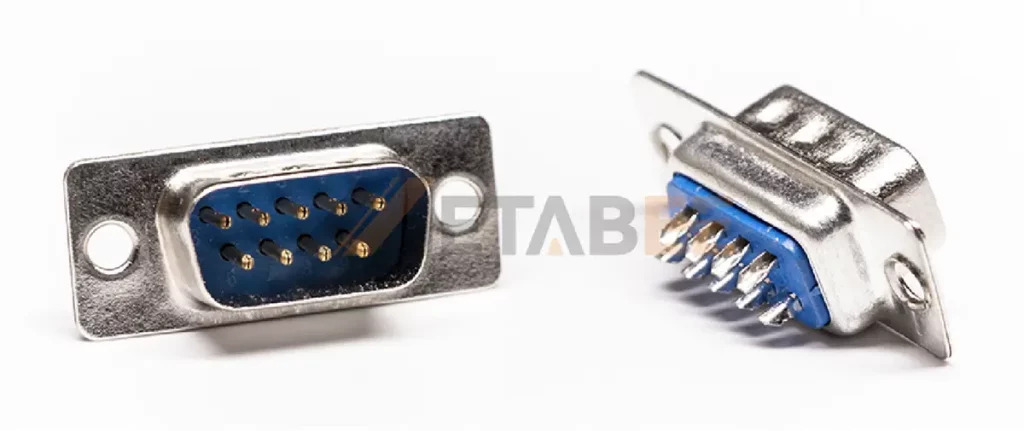
The DB9 connector is a D-subminiature connector with nine pins or sockets arranged in two rows. Technically, this nine-pin connector has a shell size of “E” and engineers correctly name it DE9, but the industry and users often refer to it as DB9. The name “DE9” comes from:
- D: Refers to the characteristic D-shaped metal shell.
- E: Originally indicated the shell size.
- 9: Represents the number of pins or sockets.
People widely use the DB9 connector in serial communications because of its small size and high reliability.
DB9 Connector Dimensions and Structure
The DB9 connector shell is shaped like the letter “D.” This shape prevents incorrect insertion and ensures the plug only fits into the socket one way. Its dimensions and structure can be described as follows:
Dimensional drawing of DB9 connector
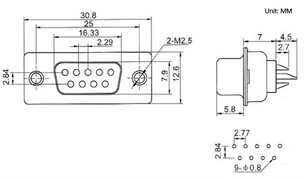
This is a sample size diagram of a straight DB9 male solder connector.
- Shell Size: The DB9 actually uses the E-size D-sub shell, with an overall width of about 30.8 mm and a height of approximately 12.6 mm.
- Pin Layout: The pin pitch is 2.77 mm. The spacing between two rows is 2.84 mm.
- Mounting Hole Distance: The distance between the two mounting hole centers is standardized at 25.0 mm. The holes are usually threaded for 4-40 UNC screws, allowing the connector to be securely attached to panels or equipment.
DB9 connector structure diagram
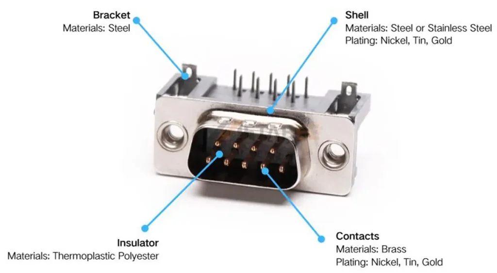
- Shell: Manufacturers typically use nickel-plated steel with a D-shaped design to provide shielding and prevent incorrect insertion.
- Insulator: Typically made of durable thermoplastic polyester plastic, it holds the contacts in place and provides electrical insulation.
- Contact: The connector includes 9 pins (male) or 9 sockets (female), usually plated with gold or tin for better conductivity and durability.
- Appendix: Includes fixing screws, mounting brackets to ensure a stable installation.
What is the RS232 protocol?
The Electronic Industries Association (EIA) first introduced the RS232 protocol (Recommended Standard 232) in 1962. It defines the electrical characteristics and signaling methods used for serial communication between devices. Its key feature is asynchronous transmission. In this case, each character is sent independently. The start bit and stop bit indicate the beginning and end of the data. Essentially, RS232 is the language, while the DB9 connector is the mouth used to speak it.
Key points about RS232:
- Communication type: Serial Communication, transmitting data bit by bit over a single channel.
- RS232 Voltage levels: Logic 1 (MARK) is between –15 V and –3 V, while Logic 0 (SPACE) is between +3 V and +15 V.
- Distance support: RS232 typically supports up to 15 meters (50 feet) at 19.2 kbps, and slower baud rates extend this range.
- Device roles: Communication occurs between a DTE (Data Terminal Equipment), such as a computer, and a DCE (Data Circuit-terminating Equipment), such as a modem.
- Connectors: RS232 can use DB25, DB9, or other connectors, depending on the equipment.
It is important to note that RS232 does not require a specific connector. Although DB9 is the most common interface for RS232, RS232 can also be implemented using DB25 or other types of interfaces.
What are the key differences between DB9 and RS232?
When it comes to serial communication, one of the most common points of confusion is the relationship between DB9 connectors and the RS232 protocol. Many users assume that DB9 and RS232 are the same thing, but in reality, they refer to two completely different aspects of a communication system.
Physical Interface vs Communication Protocol
- DB9 Connector: A DB9 is a physical plug or receptacle that connects devices electrically, creating a conductive path.
- RS232 Protocol: This protocol specifies the rules for data transmission, including voltage ranges, signal meanings, baud rates, and more. RS232 does not specify the shape or size of the connector; it only defines the “language” that devices use to communicate.
Practical Examples
In practical applications, the difference between DB9 and RS232 can be demonstrated as follows:
- A DB9 connector can transmit RS232 signals between a computer and a modem.
- The same DB9 connector can also carry CAN bus communication in automotive applications.
- RS232 protocol could be implemented using a DB25 connector, an RJ45 connector, or even a custom header on a circuit board.
This proves that DB9 and RS232 are not interchangeable terms—one is about hardware, the other about communication rules.
Why the Confusion Exists?
The confusion mainly comes from history.
When EIA first introduced the RS232 protocol in 1962, it was commonly implemented using DB25 connectors (25 pins). Later, manufacturers realized that many of those pins were rarely used, so they switched to DB9 connectors to save space and reduce cost.
As a result, people started casually referring to “RS232” as “DB9,” even though RS232 also worked with DB25 or other connector types. Over time, “DB9 = RS232” became a common but technically incorrect shorthand.
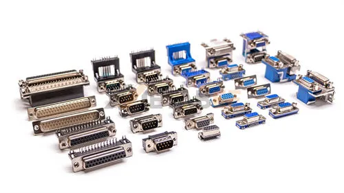
Types of RS232 DB9 Connectors
DB9 connectors come in various styles to suit different applications.
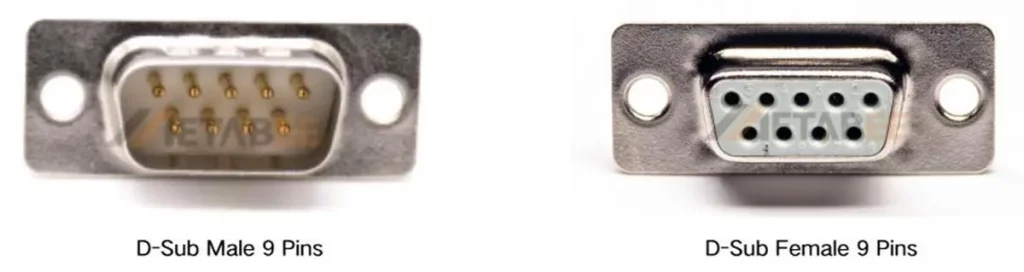
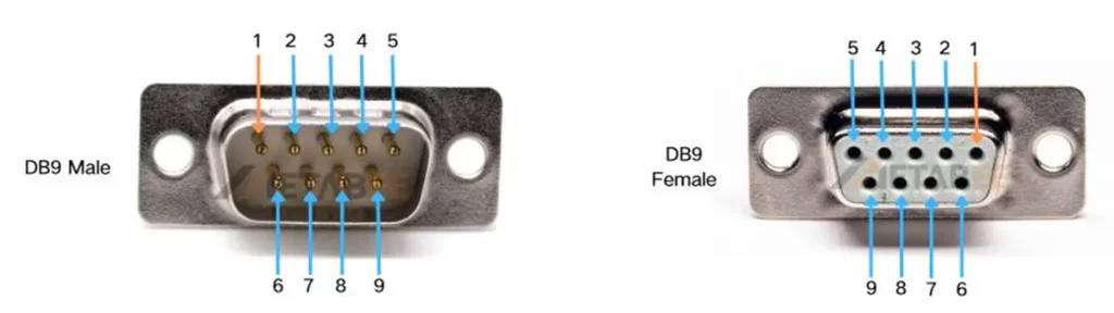
Based on Gender
- Male Connector (Plug): This connector shows nine protruding pins. It typically outputs signals.
- Female Connector (Socket): This connector has nine holes that receive pins. It typically serves as an input.
Different Mounting Styles
- Cable Mount: Cable-mounted DB9 connectors are typically fixed to cables by soldering or crimping, allowing for flexibility in making extension cables, adapter cables, or transition cables.
- Solder Cup: The solder cup DB9 connector has a small metal cup on the back of each pin, which requires the user to manually solder the wires. This method is suitable for small batch custom cables.
- Crimp: The crimping type uses a special tool to crimp the wire onto the terminal, which has a fast installation speed and high reliability, and is suitable for mass production.
- PCB Mount: Installed onto a printed circuit board by soldering, available in straight or right-angle pin configurations, commonly used for internal device connections.
- Through-Hole Mounting: Insert the connector pins into the plated through holes (PTH) drilled on the PCB, and then fix and connect them on the other side of the board through wave soldering or manual soldering.
Classification by Protection Performance
- Standard Type: Regular metal housing, suitable for everyday electronic devices.
- With EMI/RFI Shielding: Shielded housing reduces electromagnetic interference in industrial environments.
- Waterproof Type: Equipped with sealing gaskets or IP-rated protection, suitable for outdoor or harsh environments.
A Detailed Guide to the Standard RS232 DB9 Pinout
The “pinout” defines the function of each pin. For RS232, the pinout depends on whether the device is a DTE (like a PC) or a DCE (like a modem).
RS232 pinout on DB9 connector
“Pinout” actually refers to the signal corresponding to each pin number. The RS-232 protocol is defined from the perspective of the DTE. When the other end is a DCE, the direction of signals on the same pin number is reversed. Therefore, the input/output direction of the signal depends on whether the device is a DTE or a DCE.
A computer’s COM port (DTE) is typically male, while any peripheral device connected to it typically has a female connector (DCE). Because the RS-232 protocol defines signal names from the perspective of the DTE, this article focuses on the pinout of PC serial ports.
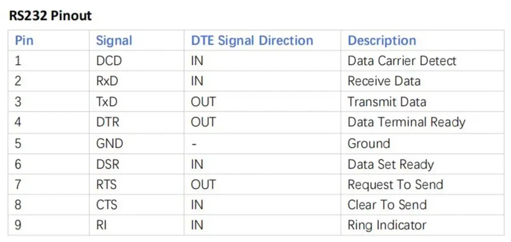
Note: Most systems use only three wires for asynchronous data communication. In such cases, only Pin 2 (TXD), Pin 3 (RXD), and Pin 5 (GND) are essential, while the remaining pins are less significant.
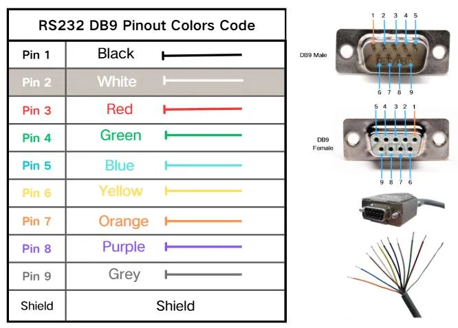
RS232 DB9 Pinout Color Code
There’s no official color code for RS232 wiring, but most pre-made cables use a common standard. Disclaimer: Because manufacturers use different color coding, always verify connections with a multimeter.
Applications of the DB9 connector
The combination of DB9 and RS232 remains important in many fields thanks to its reliability and simplicity.
Industrial Automation and Control
Engineers rely on RS232’s noise resistance in noisy factories. DB9 connectors link PLCs, CNC machines, sensors, and other equipment, keeping systems stable.
Console Ports on Network Equipment
Most enterprise routers, switches, firewalls, and servers include a DB9 console port (sometimes via an RJ45 adapter). This gives administrators direct, out-of-band access to the command line for initial setup or emergency recovery.
Interfaces for Business and Research Equipment
Many specialized devices still rely on DB9 for stable data transfer. Examples include printers and scanners in POS systems, medical equipment for data logging, and laboratory instruments that connect to control computers.
Types of the DB9 RS232 Serial Cable
The internal wiring of the cable determines how you can use it. There are two primary types.
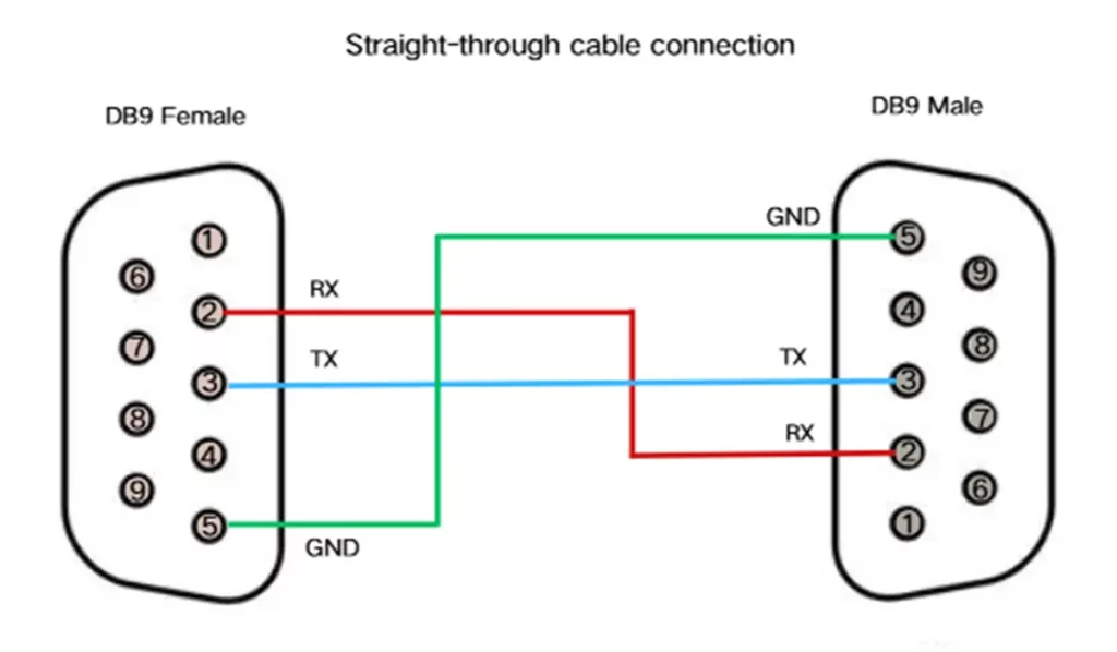
DB9 Straight-Through Cable
Straight-through cable is the most common type of serial cable. It connects each pin on one end to the same corresponding pin on the other end (pin 1 to pin 1, pin 2 to pin 2, etc.). It is used to connect a DTE (e.g., a computer) to a DCE (e.g., a modem).
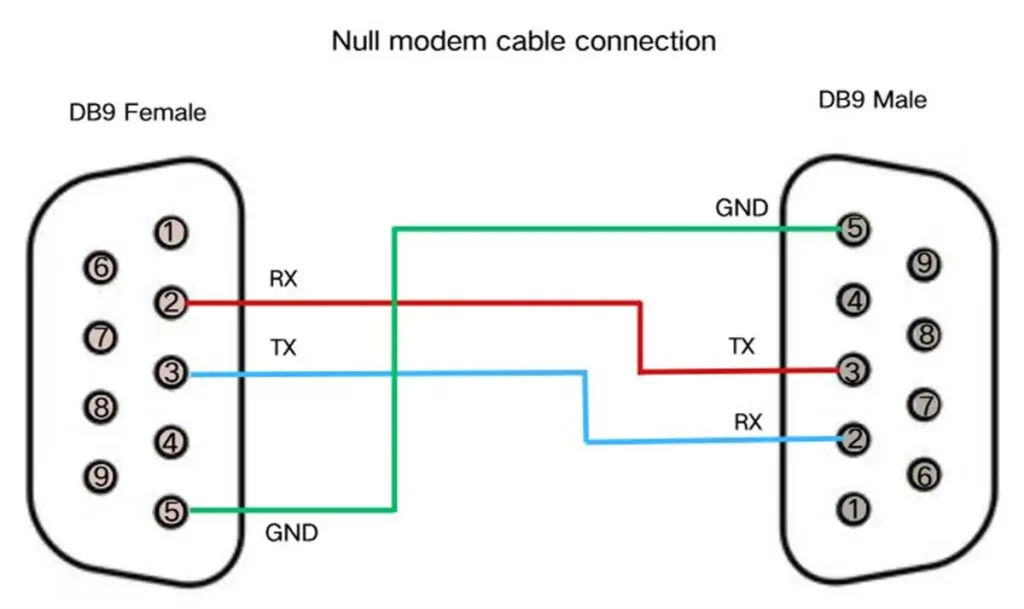
DB9 Null Modem (Crossover) Cable
A null modem cable is a special cable used to connect two DTE devices directly to each other. Transmit data (TXD) and receive data (RXD) are cross-connected at both ends, so that the transmitter of one device is connected to the receiver of the other. This is essential for PC-to-PC communication or for connecting a PC to a device that also has a DTE pinout.
How to identify straight-through cables and crossover cables?
To determine whether a serial cable is straight-through or crossover, you can use a multimeter for continuity testing. Check the connections of corresponding pins on both ends: if pin 2 connects to pin 2 and pin 3 connects to pin 3, it is a straight-through cable; if pin 2 connects to pin 3 and pin 3 connects to pin 2, it is a crossover cable. Because the outer layer of the cable is usually covered with insulating rubber, it can be difficult to insert the multimeter probes directly. It is recommended to use a short piece of solder wire as an extension contact during testing. In practice, every serial cable should be tested before use to avoid connection errors.
How to Correctly Connect RS232 Devices to a DB9 Serial Port?
- Identify Your Devices: First, figure out whether your device is DTE or DCE. A PC is always DTE, but for other equipment, check the manual.
- Choose the Right Cable: For DTE to DCE (e.g., PC to modem), use a straight-through cable. For DTE to DTE (e.g., PC to PC), you’ll need a null modem (crossover) cable.
- Make the Physical Connection: Plug one end of the DB9 connector into your computer’s serial port (or a USB-to-RS232 adapter). Then, connect the other end to your device’s DB9 port.
- Configure the Software Settings:Both devices must use exactly the same communication parameters. In your terminal software, set the baud rate (e.g., 9600), data bits (usually 8), parity (commonly “None”), and stop bits (usually 1).
- Use a Loopback Test: A loopback plug connects the TXD pin to the RXD pin on the same port. If you can send characters in your terminal and see them echoed back, it confirms that your port and PC are working.
Conclusion
When it comes to DB9 and RS232, many people mistake them for the same thing—but they’re not. DB9 is simply a connector, the familiar 9-pin D-Sub connector commonly found on older PCs and industrial equipment. RS232, on the other hand, is a communications protocol that defines the rules for transmitting data between devices.
This distinction also explains why many people confuse the two. RS232 signals often travel through a DB9 connector, but DB9 itself is not limited to RS232. Depending on the application, a DB9 interface can also support other serial standards or custom wiring.
Related Products
- D-Sub Connectors
- DB9 connectors
- DB9 Cable Mount Connectors
- DB9 PCB Mount Connectors
- DB9 Right Angle Male Connectors
- IDC D-Sub Female Connectors
- Combo Connector
- WaterProof D-Sub Connectors
- Stacked D-Sub Connectors
Frequently Asked Questions [FAQ]
Q1: My laptop doesn’t have a DB9 port. How can I connect to an RS232 device?
Answer: The standard solution is to use a USB to DB9 adapter. Once you install the included driver, it will create a “new” serial port on your computer for your software to communicate with the device.
Q2: What is the maximum effective transmission distance for RS232 communication?
Answer: According to the RS232 standard, the official recommended transmission distance is generally 15 meters (approximately 50 feet). The inverse relationship between transmission distance and baud rate (data rate) is that the lower the baud rate, the longer the transmission distance. Using a quality shielded RS232 serial cable can properly extend how far you can transmit data.
Q3: Can the DB9/RS232 port power the device?
Answer: The standard RS232 protocol does not include provisions for powering external devices. Its RS232 voltage is used only for signal transmission. While some pins (such as DTR/RTS) can supply a small amount of current, this is not intended for use, and devices that rely on this power supply are unreliable. Any device connected via RS232 requires its own independent power supply.
Q4: Are RS232 and COM ports the same thing?
Answer: Not exactly. A COM port is a logical interface on a PC; it simply provides routing. RS232, on the other hand, is a standard that defines the signals and voltage levels used in serial communication; it’s the actual communication language.
Pingback: DB9 to DB25 Pinout and Wiring Explained - MetabeeAI