In the vast ecosystem of modern electronics and telecommunications, few components are as ubiquitous yet as critical as the RJ45 connector. From the server racks in hyperscale data centers to the Wi-Fi router sitting on your office desk, this humble interface serves as the primary gateway for wired data transmission.
For procurement managers, electronics engineers, and system integrators, understanding the “what” is simple. But understanding the “which”—which type, which shielding class, and which performance category is right for a specific PCB design—is a complex challenge that directly impacts product reliability and network speed.
This comprehensive guide dives deep into the world of RJ45 connectors (technically known as 8P8C modular connectors). We will explore their anatomy, dissect the differences between Cat5e, Cat6, and Cat8 performance, and provide a technical roadmap for choosing the right connector for your next manufacturing project.
- What is an RJ45 Connector? Defining the Standard
- The Structure and Materials of an RJ45 Connector
- Male Plugs vs. Female Jacks: Understanding the Difference
- Classifying RJ45 Connectors: Types and Variations
- Wiring Standards: T568A vs. T568B
- Performance Categories: From Cat5e to Cat8
- Application Fields
- How to Choose the Right RJ45 Connector for Your Project
- Conclusion: The Backbone of Connectivity
- Frequently Asked Questions (FAQ)
What is an RJ45 Connector? Defining the Standard
At its core, an RJ45 connector is a standardized physical interface used for connecting telecommunications and data equipment. The term “RJ” stands for Registered Jack, a standard originally standardized by the FCC in the 1970s for telephone interfaces.
While the industry universally uses the term “RJ45,” the technically accurate description for the Ethernet connector we use today is 8P8C (8 Position, 8 Contact).
- 8 Position: The housing is designed to accommodate 8 wires.
- 8 Contact: All 8 positions contain metal contacts that transmit electrical signals.
This distinction is important because the original telephone “RJ45” (RJ45S) was slightly different mechanically. However, in today’s commercial context, “RJ45” and “8P8C Ethernet connector” are synonymous.
Why It Matters
The RJ45 connector is the termination point for twisted-pair cabling (like Cat5e or Cat6). It determines the quality of the physical connection between a device (like a computer or PLC) and the network. A poor-quality connector can cause signal loss (attenuation), crosstalk (interference between wires), and ultimately, packet loss or reduced network speeds.
The Structure and Materials of an RJ45 Connector
To select the right component, you must understand what goes into its construction. A high-quality RJ45 connector incorporates precision-engineered materials to withstand thousands of mating cycles and harsh environmental conditions.
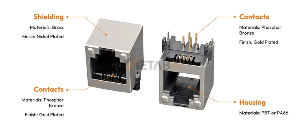
A. Housing Materials: The Body
Manufacturers typically make the outer shell of an RJ45 jack from high-temperature thermoplastics.
- Materials: Common choices include PBT (Polybutylene Terephthalate) or PA66 (Nylon 66).
- Flammability Rating: For industrial and safety-critical applications, the housing must meet UL94 V-0 standards, meaning it self-extinguishes within 10 seconds on a vertical specimen.
- Color: While black is standard for PCB jacks, they can be customized in various colors (yellow, green, blue) to color-code different network segments.
B. The Contacts: The Heart of Connectivity
The metal pins inside the jack are responsible for transmitting data. They are usually made of Phosphor Bronze, an alloy known for its excellent fatigue strength and elasticity. This ensures the pins spring back to their original position after a plug is removed.
The Critical Role of Gold Plating
Exposed copper naturally oxidizes, forming a resistive layer that can compromise signal integrity. To prevent this, the critical contact surfaces are plated with gold. The thickness of this gold plating is a major cost driver and quality indicator:
- Flash Gold: Very thin layer, suitable only for disposable or extremely low-cycle applications.
- 3u” to 6u”: Budget-friendly, suitable for equipment that is rarely unplugged.
- 15u” to 30u”: The industry standard for enterprise networking equipment.
- 50u”: The gold standard (literally). Essential for Telco specs and harsh environments, ensuring reliability over hundreds of mating cycles.
C. The Locking Mechanism
The “click” you hear when inserting a cable is the locking tab engaging. In the female jack design, the retention strength is critical. A high-quality jack ensures the cable cannot be pulled out accidentally by vibration or minor tension, a key requirement in industrial automation.
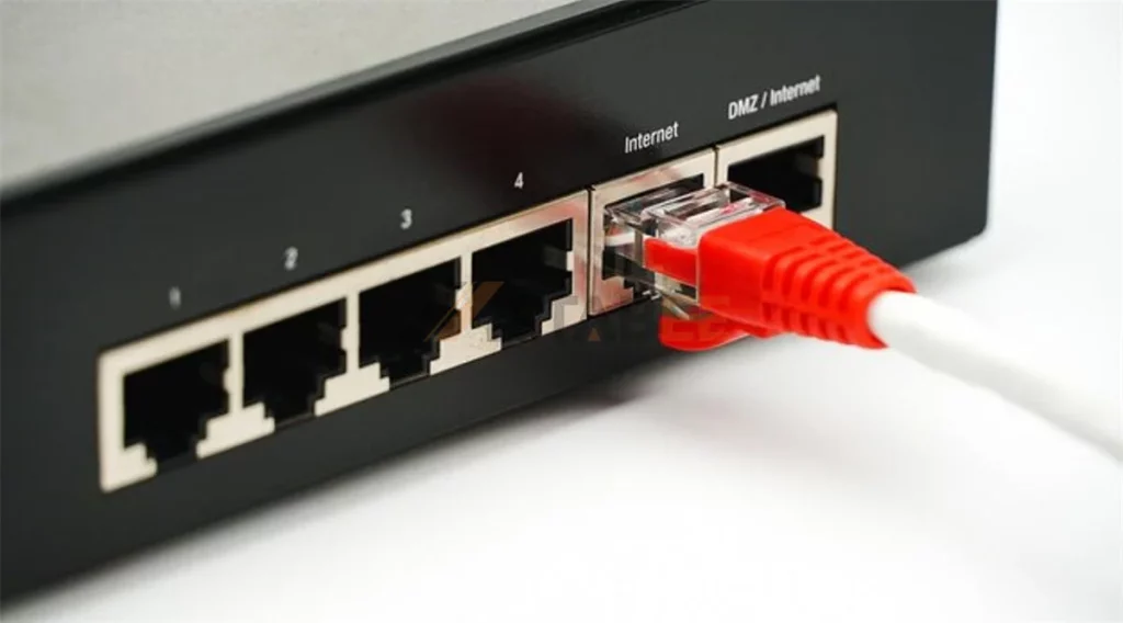
Male Plugs vs. Female Jacks: Understanding the Difference
Confusion often arises between the “connector” on the cable and the “connector” on the board.
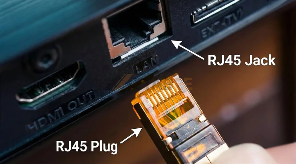
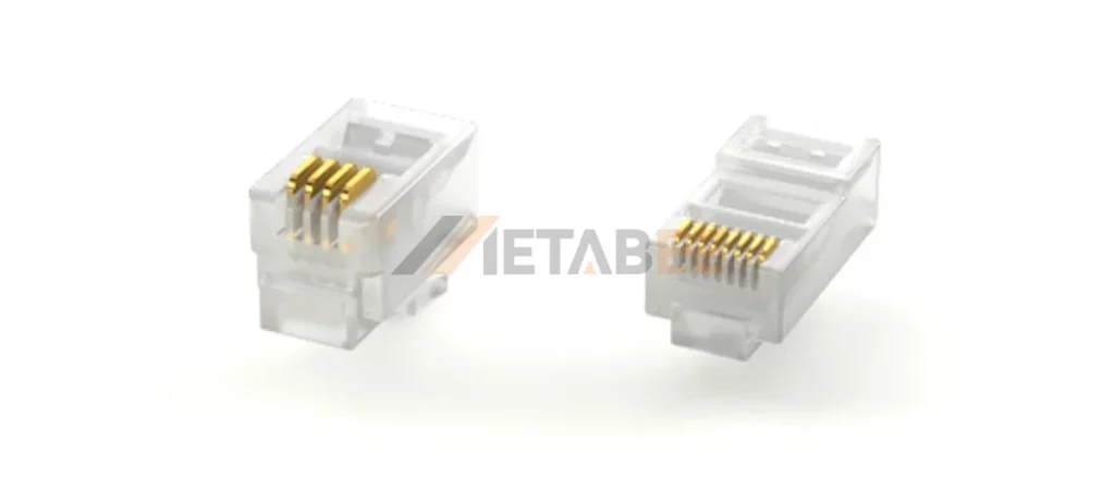
RJ45 Male Plug (Modular Plug)
This is the clear plastic component crimped onto the end of an Ethernet cable. It contains the pin blades that pierce the wire insulation. Plugs come in various designs for solid or stranded wire, and for different cable diameters (Cat5e vs. Cat6A).
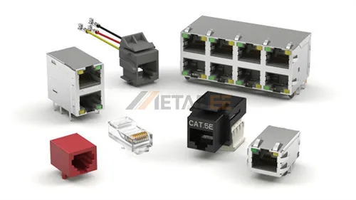
RJ45 Female Jack (Modular Jack)
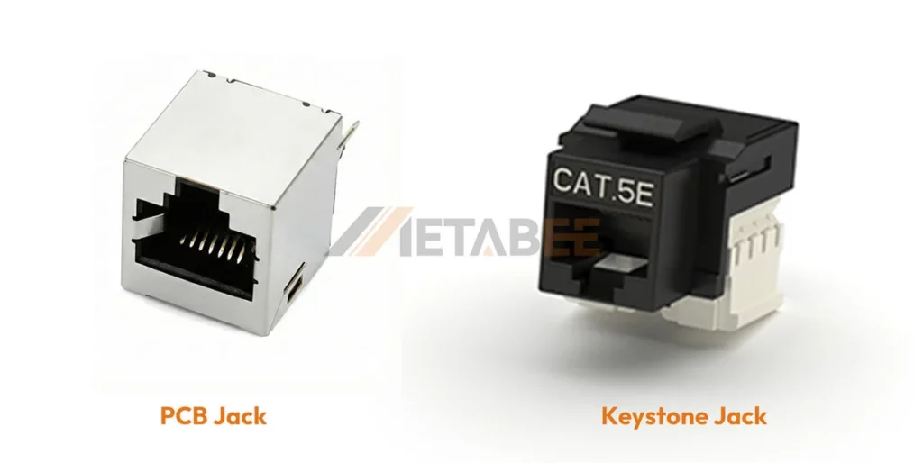
This is the receptacle that accepts the plug. This article focuses primarily on this category, as it is the component soldered onto PCBs (Printed Circuit Boards) by device manufacturers.
- PCB Jacks: Soldered directly onto the motherboard of routers, switches, or PC peripherals.
- Keystone Jacks: Snap-in modules used in wall plates and patch panels for building infrastructure.
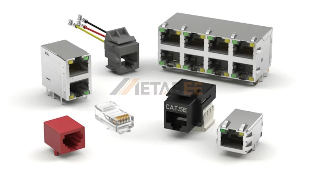
Classifying RJ45 Connectors: Types and Variations
One size does not fit all. The RJ45 landscape is vast, with thousands of variations designed to solve specific mechanical and electrical challenges.
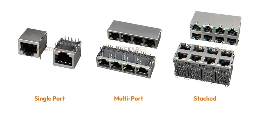
By Port Configuration (Port Density)
Space is premium real estate on a PCB. Manufacturers offer “Ganged” jacks to maximize port density.
- Single Port (1×1): The standard for consumer devices like laptops or IP cameras.
- Multi-Port (1xN): 1×2, 1×4, 1×8 configurations side-by-side. Common in consumer switches and set-top boxes.
- Stacked (2xN): 2×1, 2×2, 2×4, 2×6, or even 2×8. These “Tower” jacks are the standard for enterprise 24-port or 48-port switches, allowing double the density in the same horizontal width.
By Mounting Style
- Through-Hole (THT): The pins go through the PCB and are soldered on the opposite side. This provides the strongest mechanical bond, ideal for connectors that will be plugged/unplugged frequently.
- Surface Mount (SMT): The connector sits on top of the PCB. This allows for higher density components on the board and faster automated assembly, but mechanical strength relies heavily on solder pads and hold-downs.
- Through-Hole Reflow (THR): A hybrid method allowing THT components to be soldered using the SMT reflow process.
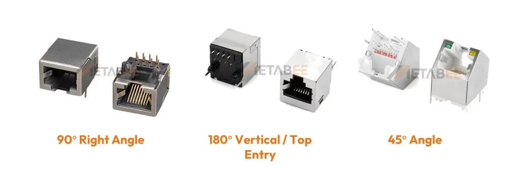
By Orientation
- Right Angle (90°): The most common type. The jack sits parallel to the PCB, and the cable exits horizontally.
- Vertical (180° / Top Entry): The cable plugs in from the top, perpendicular to the PCB. Often used in industrial control units where cable routing comes from above.
- 45° Angle: Specialized for angled faceplates to reduce cable strain.
By Shielding: UTP vs. STP
- Unshielded (Plastic Housing): Used for UTP (Unshielded Twisted Pair) cables. Sufficient for general office and home environments where electromagnetic interference (EMI) is low.
- Shielded (Metal Shell): The plastic housing is encased in a metal shell (usually nickel-plated brass). This shell connects to the cable shield and the PCB ground.
Why use it? Essential for factories, hospitals, and radio towers to prevent EMI/RFI from corrupting data. It also prevents the connector itself from emitting radiation.
Integrated Magnetics (ICM)
In standard designs, the isolation transformer and choke coils are separate chips on the PCB. RJ45 connectors with Magnetics (MagJacks) integrate these components inside the connector housing.
Benefits: Reduces component count, saves significant PCB space, and improves signal integrity by keeping the path between the magnetics and the contacts as short as possible.
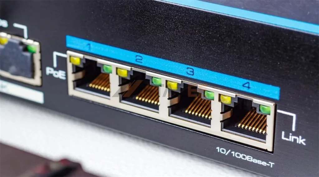
LED Indicators
Many RJ45 PCB jacks feature built-in LEDs (typically Green and Yellow).
- Green: Often indicates “Link” (connection established).
- Yellow/Amber: Often indicates “Activity” (data transmitting) or Speed (e.g., ON for Gigabit).
- Customization: METABEE can customize the LED color combination to match your device’s UI logic.
Wiring Standards: T568A vs. T568B
While the connector hardware (the jack) is usually identical, two specific color codes (T568A and T568B) dictate how the 8 wires connect into the plug.
- T568B: The dominant standard in the United States and most commercial installations. If you are making a standard patch cable, you likely use this.
- T568A: Historically required for U.S. government contracts and some residential wiring.

Does it matter for the connector buyer? For the PCB jack buyer, the internal wiring is fixed. However, the pinout of the jack must match the Ethernet controller PHY on your board. For cable assemblers, mixing T568A on one end and T568B on the other creates a “Crossover Cable” (used for connecting PC-to-PC), though modern Auto-MDIX ports make this largely obsolete.
Performance Categories: From Cat5e to Cat8
The RJ45 connector is not just a piece of plastic; it is a tuned component that must match the frequency characteristics of the cable. Using a Cat5e jack with Cat6a cable creates a bottleneck, downgrading the entire link to Cat5e speeds.
Cat5e (Category 5 Enhanced)
- Bandwidth: 100 MHz.
- Speed: Up to 1 Gbps (Gigabit Ethernet).
- Use Case: The baseline for modern networking. Still widely used in cost-sensitive VoIP phones and basic IoT sensors.
Cat6 (Category 6)
- Bandwidth: 250 MHz.
- Speed: 1 Gbps standard; supports 10 Gbps over short distances (up to 55 meters).
- Design: Stricter specifications for crosstalk and system noise. The internal contacts are often spaced or shaped to minimize interference.
Cat6a (Category 6 Augmented)
- Bandwidth: 500 MHz.
- Speed: Full 10 Gbps up to 100 meters.
- Requirement: Shielding becomes critical here. Cat6a connectors almost always require robust metal shielding to prevent “Alien Crosstalk” (interference from neighboring cables).
Cat7 (Category 7)
- Bandwidth: 600 MHz.
- Speed: 10 Gbps.
- The Conflict: The strict ISO standard for Cat7 actually defines non-RJ45 interfaces (like GG45 or TERA). However, the market demands RJ45-compatible Cat7 solutions. These are highly shielded RJ45 connectors capable of passing 600 MHz signals, bridging the gap between standard Ethernet and high-end proprietary systems.
Cat8 (Category 8)
- Bandwidth: 2000 MHz (2 GHz).
- Speed: 25 Gbps (Cat8.1) or 40 Gbps (Cat8.2) over 30 meters.
- Use Case: Data centers connecting servers to Top-of-Rack switches.
- Construction: These connectors are heavy-duty, usually fully die-cast metal, to handle the immense heat and frequency requirements.
Summary Comparison: Cat5e vs. Cat6 vs. Cat6a vs. Cat7 vs. Cat8
To help you quickly select the right standard for your application, here is a side-by-side comparison of the key RJ45 performance categories.
| Category | Frequency (Bandwidth) | Max Data Rate | Max Distance (at Max Speed) | Typical Shielding | Primary Application |
|---|---|---|---|---|---|
| Cat5e | 100 MHz | 1 Gbps | 100 Meters | UTP (Unshielded) | Basic Home/Office LAN, VoIP |
| Cat6 | 250 MHz | 10 Gbps | 55 Meters | UTP or STP | Enterprise Gigabit, PoE Devices |
| Cat6a | 500 MHz | 10 Gbps | 100 Meters | STP (Shielded) | Data Centers, High-Speed Office |
| Cat7 | 600 MHz | 10 Gbps | 100 Meters | Screened Shielded | Industrial, High-EMI Areas |
| Cat8 | 2000 MHz (2 GHz) | 25 / 40 Gbps | 30 Meters | Fully Shielded | Data Center Server-to-Switch |
Application Fields
Where are these billions of RJ45 connectors going?
- Enterprise Networking: Core infrastructure like Network Switches, Routers, Firewalls, and Wireless Access Points (WAPs).
- Industrial Automation (IIoT): Programmable Logic Controllers (PLCs), Human Machine Interfaces (HMIs), and Industrial Vision Systems. Here, connectors often need IP67 waterproof ratings.
- Consumer Electronics: Smart TVs, Desktop Motherboards, Gaming Consoles, and Laptops (though increasingly via dongles).
- Telecommunications: VoIP Desk Phones, PBX systems.
- Surveillance: IP Cameras (PoE – Power over Ethernet capability is crucial here).
- Medical Devices: Connected diagnostic equipment requiring high-isolation magnetics for patient safety.
How to Choose the Right RJ45 Connector for Your Project
For procurement and R&D engineers, selecting the right Part Number (PN) involves asking four critical questions:
1. What is the Environmental Stress?
- Office/Home: Standard plastic Cat5e/Cat6 jacks are sufficient.
- Factory Floor: High vibration and EMI require a Shielded Jack with strong retention tabs and possibly 50u” gold plating to prevent micro-fretting corrosion.
- Outdoor: Requires IP67/IP68 waterproof RJ45 systems.
2. What is the Space Constraint?
If designing a compact blade server or a slim consumer device, look for Low Profile or Mid-Mount (sinks into the PCB cut-out) jacks. If designing a 48-port switch, Stacked (2xN) jacks are the only viable option.
3. Do You Need Integrated Magnetics?
- Yes: If you want to simplify PCB layout and reduce Bill of Materials (BOM) count. Look for “RJ45 with Magnetics” or “ICM”.
- No: If you have a specific discrete transformer you prefer, or if PCB space is not an issue, a standard “passive” jack is cheaper.
4. What is the Manufacturing Process?
Ensure the connector housing material can withstand your soldering temperature.
- Wave Soldering: Standard PBT is usually fine.
- Reflow Soldering: Requires high-temp Polyamide (PA66/PA46) or LCP materials to survive the reflow oven without melting.
If you are still unsure how to choose the right RJ45 connector, please contact us—our engineers will be happy to answer any questions you may have.
Conclusion: The Backbone of Connectivity
The RJ45 connector is a deceptively simple component that supports the weight of the world’s digital communication. Whether you are building a simple home router or a complex industrial control system, the choice of connector dictates the longevity and reliability of the device.
From the basic unshielded Cat5e jack to the high-speed, shielded Cat8 magnetic module, the variety is immense. Understanding the nuances of shielding, pin plating, and category performance ensures that your product delivers the speed and stability your customers expect.
Ready to Source High-Quality RJ45 Connectors?
At METABEE, we specialize in the design and manufacturing of precision RJ45 interconnect solutions. Whether you need a custom magnetic module for a specific chipset or a standard reliable jack for mass production, our engineering team is ready to assist.
Contact us today to request a quote, free samples, or a consultation for your next PCB design project.
Frequently Asked Questions (FAQ)
Here are the most common questions our engineering team receives about RJ45 connectors:
Q: What is the difference between RJ45 and 8P8C?
A: Technically, “RJ45” is a telephone interface standard, while “8P8C” (8 Position, 8 Contact) is the correct term for the physical connector. However, in the industry, they are used interchangeably to refer to the standard Ethernet port.
Q: Can I use a Cat6 connector with a Cat5e cable?
A: Yes, it is physically compatible, but it won’t increase your speed beyond what the cable supports. Conversely, using a Cat5e connector on a Cat6 network can create a bottleneck and reduce performance.
Q: Do I really need gold plating on the contacts?
A: Yes. Gold plating prevents oxidation, which causes signal loss. Thicker plating (e.g., 30u” or 50u”) provides better durability for ports that are frequently plugged and unplugged, whereas “flash gold” is suitable only for stationary connections.
Q: When should I use a shielded (STP) RJ45 connector?
A: You should use a shielded connector (metal casing) if your device operates in an environment with high electromagnetic interference (EMI), such as a factory floor, or if you are using shielded cables (like Cat6a) to prevent alien crosstalk.
Q: What is a “MagJack” or RJ45 with integrated magnetics?
A: This is an RJ45 connector that has transformers and chokes built directly into the housing. It saves PCB space and simplifies the circuit design by filtering noise inside the connector rather than on the motherboard.
Q: What do the LEDs on the RJ45 jack indicate?
A: While customizable, the standard is: Green for “Link” (a valid connection is established) and Yellow/Amber for “Activity” (data is being transmitted). Some jacks use colors to indicate speed (e.g., Orange for 1Gbps, Green for 100Mbps).
Q: Are RJ45 connectors waterproof?
A: Standard RJ45 connectors are not waterproof. For outdoor use or harsh industrial environments, you must specify IP67 or IP68 rated connectors, which feature sealing gaskets and waterproof caps.
Q: What is the difference between T568A and T568B wiring?
A: These are two color-code standards for arranging the wires inside the cable plug. T568B is the most common standard for commercial use. The connector jack itself is usually compatible with both; the difference lies in how the cable is assembled.
Q: Can RJ45 connectors support Power over Ethernet (PoE)?
A: Yes. Most modern RJ45 connectors can handle PoE (up to 100W for PoE++). However, for high-power applications, ensure the contact material and design can handle the arc that may occur when unplugging under load.
Q: Which is better: Through-Hole or Surface Mount (SMT)?
A: Through-Hole (THT) provides stronger mechanical retention, making it ideal for ports that face heavy user interaction. Surface Mount (SMT) allows for automated assembly and higher component density but typically requires additional hold-down tabs for mechanical strength.
Pingback: RJ45 Connector with Integrated Magnetics: Comprehensive Guide - MetabeeAI