


In the rapidly evolving world of electronics design, the pressure to make devices smaller, faster, and more reliable is constant. From Industrial IoT (IIoT) gateways to high-speed consumer gaming consoles, Ethernet remains the gold standard for reliable connectivity. However, ensuring that an Ethernet signal travels cleanly from a cable to a processor involves complex engineering.
For decades, this required a bulky arrangement of discrete components on a Printed Circuit Board (PCB). Enter the RJ45 connector with integrated magnetics.
Also frequently referred to by engineers as an RJ45 Jack with integrated magnetics, an ICM (Integrated Connector Module), or simply a MagJack, this component has revolutionized how networking hardware is designed. But what exactly is going on inside that metal shield? Why are more engineers switching from discrete magnetics to integrated solutions? And how do you select the right one for your specific PHY chip?
This comprehensive guide will cover everything you need to know about the RJ45 connector with integrated magnetics, helping you optimize your PCB layout for signal integrity, EMI suppression, and space efficiency.
What is an RJ45 Connector with Integrated Magnetics?
At first glance, an RJ45 connector with integrated magnetics looks identical to a standard, non-magnetic RJ45 jack. It has the same footprint, the same plastic housing, and the same metal shielding. However, the difference lies in what is hidden inside the housing.
A “standard” RJ45 connector is a passive mechanical pass-through. It simply connects the pins on the PCB to the contacts touching the Ethernet cable. It offers no signal conditioning or protection.
In contrast, an RJ45 connector with integrated magnetics houses a complex array of electromagnetic components directly within the connector’s body. It essentially takes the magnetic circuitry that traditionally sat on the PCB, including transformers, common mode chokes, and termination resistors. These components are then miniaturized and potted directly inside the connector shell.
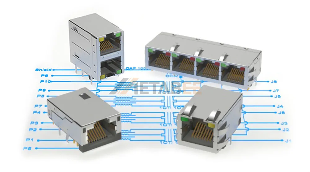
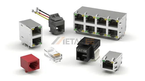
Metabee RJ45 Magnetic Jacks
Related Post: What is an RJ45 Connector? The Ultimate Guide to Types, Pinouts, and Applications
Terminology Note: Connector vs. Jack
While the industry broadly uses the term “connector,” it is worth noting that in the context of PCB design, we are specifically talking about the RJ45 Jack (the female receptacle). The “Plug” is the male end attached to the cable. Throughout this guide, we will use the terms “connector,” “jack,” and “ICM” interchangeably to refer to the PCB-mounted component.
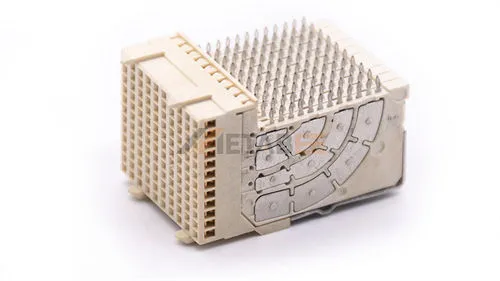
The Internal Structure of a Magnetic RJ45 Jack
If you were to cut open a magnetic RJ45 jack, you would find a microscopic marvel of winding engineering:
- Isolation Transformers: These provide galvanic isolation (typically 1500V or 2250V) between the cable side (Line side) and the chip side (PHY side). They allow the data signal to pass through via magnetic induction while blocking DC voltage and protecting the sensitive PHY chip from dangerous spikes.
- Common Mode Chokes (CMC): These are vital for Electromagnetic Interference (EMI) control. They allow differential signals (the data) to pass but present high impedance to common-mode noise (unwanted interference), filtering it out.
- Termination Resistors (Bob Smith Termination): These are used to match the impedance of the line (usually 100 ohms) to prevent signal reflection, which can corrupt data packets.
- High-Voltage Capacitor: Often included to couple the termination resistors to the ground shield, further aiding in noise suppression.
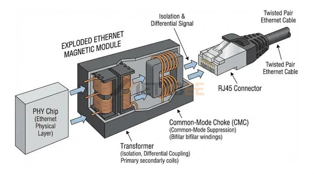
The Mechanics: How Integrated Magnetics Work
To understand the value of an RJ45 connector with integrated magnetics, one must understand the three critical functions it performs: Electrical Isolation, Signal Conditioning, and EMI Suppression.
Electrical Isolation and Safety
Ethernet cables can run for up to 100 meters. Over such distances, ground potentials can vary significantly between two devices (e.g., a router in one building and a camera in another). Without isolation, this ground loop could create dangerous currents that fry the transceiver chip or even shock a user.
The transformers inside the integrated jack decouple the local device ground from the cable ground. The signal is transferred magnetically, meaning there is no direct electrical path for DC current to flow.
Signal Integrity and Impedance Matching
Ethernet signals are high-frequency differential signals. For maximum power transfer and minimal reflection (Return Loss), the impedance must remain constant—typically 100 Ohms for twisted pair cabling.
Integrated magnetics are factory-tuned to maintain this impedance balance. Because the magnetic cores are located mere millimeters from the cable contact pins, the signal path is incredibly short. This minimizes “stubs” and parasitic capacitance that can occur when using discrete components on a PCB, resulting in cleaner “eye diagrams” and fewer packet errors.
EMI Filtering (The “FCC” Factor)
Passing EMC (Electromagnetic Compatibility) certification is often the biggest headache for hardware engineers. Ethernet cables act as long antennas that can radiate noise generated by the system (Egress) or pick up noise from the environment (Ingress).
The Common Mode Chokes inside the RJ45 jack act as a gatekeeper. They block high-frequency noise from exiting the device onto the cable and prevent external noise from entering the PHY. By placing these filters at the very edge of the PCB—right inside the connector—integrated magnetics stop noise before it even enters the board traces.
Integrated vs. Discrete Magnetics: Why Make the Switch?
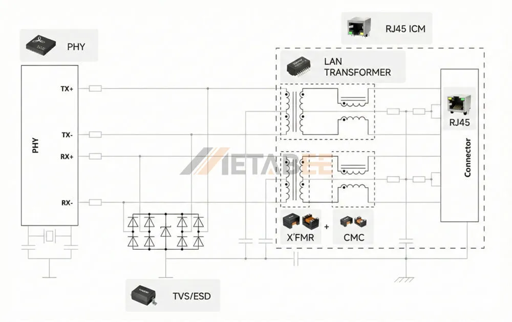
Historically, engineers would place a standard RJ45 jack on the board, followed by a separate LAN transformer module (discrete magnetics), and then the PHY chip. While this “discrete” method is still used in some niche applications, the industry has overwhelmingly shifted toward RJ45 jacks with integrated magnetics.
Here is a detailed comparison of why integration matters for your PCB design.
PCB Real Estate Savings
This is the most obvious advantage. Modern electronics are shrinking. In applications like IoT gateways, IP cameras, or high-density network switches, every square millimeter counts.
- Discrete: Requires space for the connector, the bulky transformer module, and the clearance zones between them.
- Integrated: Combines everything into the footprint of the connector itself. This can reduce the required PCB area for the Ethernet front-end by 50% to 70%.
Simplified Layout and Routing
Routing high-speed differential pairs (TX+/TX- and RX+/RX-) requires strict adherence to length matching and impedance rules.
- Discrete: You must route tracks from the connector to the transformer, and then from the transformer to the PHY. Every inch of track introduces potential for impedance mismatch and noise coupling.
- Integrated: You only need to route from the PHY to the connector. The most sensitive analog section is handled internally by the manufacturer. This simplifies the layout, reduces layer count, and speeds up the design cycle.
Reliability and MTBF
A discrete setup involves significantly more solder joints. For a standard Gigabit channel, a discrete transformer might have 24 pins, plus the connector’s pins. An integrated solution eliminates the transformer’s solder joints entirely. Fewer solder joints mean fewer points of failure, particularly in high-vibration environments like industrial automation.
4. EMI Performance Consistency
When you design with discrete magnetics, the EMI performance is heavily dependent on your PCB layout (ground planes, separation distance, etc.). With an RJ45 connector with integrated magnetics, the “field effect” is contained within the metal shield of the jack. The manufacturer has already optimized the internal layout of the coils and shields. This provides a more predictable and consistent EMI performance, making it easier to pass CE/FCC certifications on the first try.
Summary Comparison
| Feature | Integrated Magnetics (ICM) | Discrete Magnetics |
| PCB Footprint | Smallest possible footprint | Large (Connector + Transformer) |
| Design Complexity | Plug-and-Play | Complex routing required |
| Component Count | 1 Component | 2+ Components |
| EMI Shielding | Superior (contained in shield) | Variable (layout dependent) |
| Cooling | Moderate heat dissipation | Better airflow (components spread out) |
Are There Any Downsides to Integrated Magnetics?
While integrated connectors are the gold standard for most modern designs, it is important to understand the trade-offs to make an informed decision:
- Repairability: In the rare event of a lightning surge damaging the magnetic coils, an integrated solution requires replacing the entire connector. With discrete components, you might only need to replace the standalone transformer, which can be cheaper and less invasive during repair.
- Second-Source Compatibility: Finding a “drop-in” replacement for a specific MagJack can be challenging if a manufacturer discontinues a part (EOL). Unlike standard RJ45 jacks, which have standardized footprints, integrated jacks often have unique pinouts depending on the internal schematic. This makes supply chain management slightly more critical.
- Extreme Isolation Needs: For specialized medical or utility-grade applications requiring isolation voltages far beyond standard limits (e.g., >4kV), discrete transformers often offer a wider range of high-voltage options than standard integrated jacks.
Key Features to Consider When Choosing an RJ45 Magjack
Not all magnetic jacks are created equal. When browsing a catalog, you will encounter various specifications. Here is what they mean and how to choose.
Data Speed Standards
The magnetic windings must be tuned to the frequency of the data transmission.
- 10/100Base-T: Uses 2 pairs of wires. Suitable for simple IoT sensors.
- 1000Base-T (Gigabit): Uses all 4 pairs of wires. The magnetics are more complex. This is the current standard for most consumer electronics.
- 2.5G / 5G / 10GBase-T: Requires extremely high-performance magnetics with minimal cross-talk. Used in high-end Wi-Fi 6 access points and servers.
- Tip: A Gigabit connector can usually handle 10/100 traffic (backward compatible), but a 10/100 connector generally cannot handle Gigabit speeds.
Power over Ethernet (PoE) Capability
This is a critical specification. With the rise of PoE cameras and VoIP phones, many RJ45 jacks need to transmit power alongside data.
- Non-PoE: The wire coils are thin and designed only for data signals.
- PoE / PoE+ / PoE++: The magnetics are built with thicker wire gauges and special core materials to handle DC current without saturating (which would block the data signal).
- Selection Rule: If your device supplies power (PSE) or receives power (PD), you must select a PoE-rated RJ45 connector with integrated magnetics. Using a non-PoE jack in a PoE circuit will result in overheating and component failure.
Shielding and EMI Fingers
- Shielded: Has a metal casing (usually brass or stainless steel) connected to the PCB ground. This acts as a Faraday cage.
- EMI Fingers: Look for “spring fingers” or tabs on the face of the shield. These press against the device’s chassis/panel, creating a continuous ground connection to discharge static and block noise.
LED Indicators
Most integrated jacks come with built-in LEDs (typically Green and Yellow) to indicate Link Status and Activity. Using integrated LEDs saves you from having to place separate light pipes or surface-mount LEDs on the PCB.
Still unsure which RJ45 connector to choose? Contact our technical team today—Metabee is here to provide expert selection guidance and technical support.
Common Applications and Industries
The RJ45 connector with integrated magnetics has become the go-to solution across nearly every industry that utilizes wired networking.
Industrial Automation
In factories, motors and heavy machinery generate massive amounts of electrical noise. Industrial PLCs (Programmable Logic Controllers) and HMI panels rely on magnetic jacks with high common-mode rejection to ensure that control signals aren’t corrupted by the welding robot next door. The vibration resistance of a single soldered component (the ICM) is also a major plus here.
Telecommunications and Networking
Network switches, routers, and servers use “Gang Jacks” (multi-port RJ45 connectors with integrated magnetics, such as 2×1, 2×4, or 2×6 configurations). These high-density modules allow manufacturers to pack 48 ports into a 1U rack space—something impossible with discrete magnetics.
Consumer Electronics
From Smart TVs and set-top boxes to the latest gaming consoles, consumer devices require compact, cost-effective components. The integration allows for slimmer device profiles and lower assembly costs.
Internet of Things (IoT)
IoT Gateways often act as the bridge between wireless sensors and the cloud. These devices are usually small form-factor. An RJ45 jack with integrated magnetics is essential to fitting an Ethernet port onto a credit-card-sized PCB.
Selection Guide: Matching the Connector to the PHY
This is the most technical part of the selection process and where most mistakes happen. You cannot simply grab any generic magnetic jack and expect it to work with your specific Ethernet Controller (PHY). You must match the magnetics to the chip’s requirements.
Current Mode vs. Voltage Mode Drive
Ethernet PHY chips output signals in different ways:
- Current Mode Drive: The PHY sinks current. The center tap of the transformer on the PHY side usually needs to be connected to the voltage supply (Vcc like 3.3V).
- Voltage Mode Drive: The PHY drives voltage. The center tap on the PHY side is usually connected to a capacitor to ground.
If you buy an RJ45 connector wired for a Current Mode PHY and connect it to a Voltage Mode PHY, it will not work (or will burn out). Always check your PHY datasheet for the recommended magnetic schematic and match it to the connector datasheet.
Turns Ratio
The turns ratio (e.g., 1:1, 1CT:1CT, or 1:2.4) determines the voltage transformation between the primary and secondary windings.
- Most modern PHYs require a 1:1 turns ratio for both Transmit (TX) and Receive (RX).
- However, some older or specialized PHYs may require different ratios. Using the wrong ratio will result in signal amplitude issues.
Auto-MDIX
Most modern systems support Auto-MDIX (automatic detection of straight-through or crossover cables). For this to work efficiently, the internal magnetics of the connector usually need to be symmetrical on the TX and RX channels.
Pinout Compatibility
There is no single “standard” footprint for RJ45 connectors with integrated magnetics. Different manufacturers have different pin spacing and layouts.
Tip: If you are second-sourcing a part (finding a backup supplier), you must overlay the mechanical drawings carefully to ensure the pins for LEDs and signal lines align perfectly with your existing PCB layout.
Conclusion
The shift from discrete magnetic components to the RJ45 connector with integrated magnetics represents a maturation of Ethernet hardware design. By encapsulating complex EMI filtering, isolation, and impedance matching circuitry into a single robust housing, these components offer engineers a “plug-and-play” solution for high-speed connectivity.
Whether you are designing a rugged industrial sensor, a sleek consumer gadget, or a high-power PoE surveillance system, choosing the right RJ45 jacks with integrated magnetics is critical to your product’s success. It saves PCB space, simplifies routing, and ensures your device passes EMC testing with flying colors.
Ready to optimize your next Ethernet design? Don’t let signal integrity issues slow you down. Contact our engineering support team today for help matching the perfect connector to your PHY chipset.
Frequently Asked Questions (FAQ)
Q: Can I use a 10/100 integrated connector for a Gigabit application?
A: No. A 10/100 connector typically only contains magnetics for two pairs of wires (Pins 1,2,3,6). Gigabit Ethernet (1000Base-T) utilizes all four pairs (Pins 1-8). You need a connector specifically rated for 1000Base-T to get Gigabit speeds.
Q: Are RJ45 connectors with integrated magnetics more expensive than discrete solutions?
A: If you look at the raw component price, an integrated jack might seem more expensive than a basic jack + a discrete transformer. However, when you factor in the Total Cost of Ownership (TCO)—including PCB space savings, reduced assembly pick-and-place costs, simpler inventory management, and higher yield rates—the integrated solution is almost always more cost-effective for modern designs.
Q: Do integrated magnetics overheat in PoE applications?
A: They can if underspecified. Because the components are enclosed in plastic and metal, heat dissipation is lower than discrete components exposed to air. For high-power applications (like PoE++ Type 3 or Type 4, delivering 60W or 100W), it is crucial to select an RJ45 connector with integrated magnetics designed with special high-temperature wire and potting compounds to manage the thermal rise.
Q: What is the lifespan of a MagJack?
A: Like standard connectors, they are rated for mating cycles (typically 750+ insertions). The internal magnetic components are solid-state and passive, meaning they do not “wear out” electrically under normal operating conditions. The failure point is usually mechanical (bent pins) rather than magnetic.
Q: What is the standard isolation voltage for these connectors?
A: The industry standard is typically 1500Vrms or 2250VDC for 60 seconds. This meets the IEEE 802.3 safety requirement to protect the PHY and the user from high-voltage transients that might occur on the network cable.
Q: Should I connect the metal shield of the connector to my PCB ground?
A: Yes. For effective EMI suppression, the metal shield tabs (EMI fingers) must be connected to the chassis ground or a dedicated shield ground on your PCB. This provides a path for noise to drain away rather than radiating into the circuitry.
Q: What is “Bob Smith Termination” mentioned in some datasheets?
A: Bob Smith Termination is a specific circuit design used inside the connector to reduce “common-mode” noise. It involves connecting the unused pairs (in 10/100) or the center taps (in Gigabit) to ground via a 75-ohm resistor and a high-voltage capacitor. Most modern integrated jacks include this circuitry automatically.
Q: Can I use reflow soldering for RJ45 connectors with integrated magnetics?
A: It depends on the specific model. Most standard “Through-Hole” RJ45 jacks are wave-solder only because the high heat of a reflow oven can melt the plastic housing or damage the internal magnetics. However, special “Reflow Compatible” or “Pip-in-Paste” versions exist that use high-temperature thermoplastics (like LCP). Always check the datasheet for the “Solder Profile.”